Shunlongwei Co. ltd.
IGBT Module / LCD Display Distributor
Customer Service
+86-755-8273 2562
IGBT Module / LCD Display Distributor
“Brushless DC motors do not require physical contact between the brushes and the commutator. This step eliminates mechanical losses caused by friction, making brushless DC motors more suitable for long-term use. Since the rotor does not need power, brushes and slip rings are not required, and the commutator assembly also simplifies the structure. This also allows brushless DC motors to deliver more torque per watt than brushed DC motors in a smaller package.
“
By Cristian Ionescu-Catrina, Senior Product Marketing Manager, Power Integrations
Electric motors are currently the largest electricity consumers in the world, and they account for a very large proportion. The Energy Research Centre of the Netherlands (ECN) estimates that 45% of global electricity generation is consumed by electric motors. Therefore, in order to promote the improvement of efficiency, countries are adopting legislative means to improve the efficiency standards of electric motors. In July 2021, the European Union began implementing the Electric Motors and Variable Speed Drives Regulation (EU) 2019/1781, adding minimum efficiency limits for some motors that were previously excluded from the standard and shortening the compliance efficiency for other types of motors. Request the reserved time. The trend shown by such regulations is clear that the minimum efficiency allowed by C will continue to increase over time. New motor designs should be as efficient as possible to avoid the risk of being forced to be replaced by legislation before the end of their working life.
These laws cover a wide variety of motors, from large motors in infrastructure pumps to tiny motors that power PC fans. Size is not the only consideration – the type of motor is also important. Previously, brushed DC motors were widely used, but they were relatively inefficient and had limited reliability. C brushes would wear out over time and need to be replaced. The need for higher efficiency and greater reliability at various operating speeds and loads has led to the widespread adoption of brushless DC (BLDC) motors in new designs.
Brushless DC motors do not require physical contact between the brushes and the commutator. This step eliminates mechanical losses caused by friction, making brushless DC motors more suitable for long-term use. Since the rotor does not need power, brushes and slip rings are not required, and the commutator assembly also simplifies the structure. This also allows brushless DC motors to deliver more torque per watt than brushed DC motors in a smaller package.
Brushless DC motors use permanent magnets as the rotor, which interact with the electromagnetic field generated by the stator coils. These coils turn on and off in precise patterns to ensure efficient rotor rotation. This mode is determined by a microcontroller (MCU) algorithm and uses sensors embedded in the motor to provide real-time feedback for precise control. The microcontroller sends a signal to the switch, which controls the current flow through the coil. Although microcontroller control adds some complexity to the motor drive, it provides a greater degree of flexibility and precision.
Since the regulatory standards for motor efficiency refer to the operation of the entire motor assembly, it is necessary to optimize the operation of each stage to minimize overall losses. This includes the inverter used to power the motor. Inverter performance is limited by heat. In addition to shortening the life of the inverter, poor thermal performance can prevent the inverter from supplying sufficient current to the motor drive when the drive overheats. The typical solution to cooling problems is to use a heatsink, or in some cases an auxiliary fan, but neither solution is ideal. Both will increase the size and weight of the motor, which is not conducive to realizing the miniaturization of the motor, and will increase the number of BOM materials, increase the complexity of the design, and reduce the mechanical strength of the design.
Power Integrations (PI) C has extensive experience developing highly integrated high voltage ICs for off-line power conversion and gate drive – and can approach this problem from two different directions. The first is to provide an efficient architecture that minimizes the amount of heat that needs to be dissipated. The second approach is to use separate ICs to drive the motor windings for each phase to provide a scalable solution that is flexible enough to support single-phase and multi-phase motors. The small amount of heat generated by the losses of each driver is evenly distributed over the entire PCB, rather than concentrated in a single hot spot.
This is our BridgeSwitch™ family of integrated half-bridge (IHB) motor drivers, suitable for driving synchronous motors (brushless DC or permanent magnet synchronous motors (PMSM)) as well as asynchronous motors (eg AC induction motors). BridgeSwitch devices can achieve efficiencies as high as 98.5% and are suitable for power ranges up to 30W (typ. IRMS = 0.2A) to 400W (typ. IRMS = 1.1A) for the inverter design. BridgeSwitch ICs integrate low- and high-side drivers, controllers, level shifters, and two N-channel 600V fast-recovery epitaxial diode FETs (FREDFETs) with lossless current sensing. FREDFETs have extremely fast recovery body diodes, making them ideal for driving inductive loads. They significantly reduce switching losses and feature soft recovery to reduce EMI.
BridgeSwitch ICs are self-powered, allowing simpler system power supplies such as PI’s LinkSwitch™-TN2 to drive microcontrollers. Small non-isolated drivers can be used instead of the multiple-output isolated flyback approach in traditional designs, further reducing BOM, design complexity, and board space. The inverter diagnostic function is also integrated inside, which can reduce the number of sensors required and the proportion of microprocessor fault processing resources. BridgeSwitch ICs integrate many hardware-based fault protection and external system-level monitoring functions. Not only does this hardware approach provide faster response than software protection, but it is easier to pass UL/IEC 60730 certification because the architecture has hardware-based cycle-by-cycle down- and upper-tube overcurrent protection and on-board monitoring. Implementing these functions in hardware means that the software requirements to meet UL/IEC 60730 are reduced from Class B to Class A, without the need for recertification after a software update.
To get designs to market faster, PI has also developed several brushless DC motor reference design kits (RDKs) for the BridgeSwitch product family. The new reference design delivers up to 400W of output power without a heat sink, enabling applications with higher RMS current requirements and high heat dissipation requirements, such as compressors, range hoods, and domestic and commercial fans and pumps.
|
|
The RDK-851 is a 50W high voltage brushless DC motor control design using the BridgeSwitch IC BRD1260C for fan applications. This three-phase inverter with control input interface provides over 93% efficiency. The design uses an 88mm diameter PCB. |
|
|
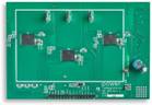
The RDK-852 is a three-phase brushless DC motor driver for pump applications up to 200W. The design has a PCB board size of 65mm x 50mm and uses the BridgeSwitch IC BRD1263C with a sensorless Field Oriented Control (FOC) method. This 97% efficient solution also uses the LinkSwitch-TN2 IC (LNK3204D) to power the current-sense amplifier and optionally provides an external bias supply for the BridgeSwitch device. |
|
|
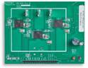
The RDK-853 is an excellent 300W compressor three-phase motor drive solution that is over 98% efficient over the entire load range and features a 95mm x 75mm PCB. The solution uses the BridgeSwitch IC BRD1265C and LinkSwitch-TN2 LNK3204D IC, which have a signal interface that provides transient phase current output signals and fault reporting for each BridgeSwitch device, enabling sensorless FOC control from any microcontroller. |
|
|
PI also offers a single-phase brushless DC motor driver reference design. The RDK-872 is a 70W design with 97% efficiency. This single-phase inverter uses two BridgeSwitch BRD1261C ICs in a low profile surface mount package with exposed pads for heat dissipation through the PCB. |
|
|
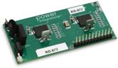
The RDK-873 is a 30W compact brushless DC motor driver with up to 95% efficiency. The inverter power stage uses two BridgeSwitch BRD1260C motor driver ICs and is a full-bridge inverter design. |
None of these boards require a heat sink.
To further simplify the design process, PI has introduced Motor-Expert™, a motor control configuration and diagnostic application that provides a graphical user interface for all parameters and commands, as well as an interface for interacting with the motor controller in serial mode Terminal emulator. The Motion Scope feature provides a linear graph of important controller variables that can be viewed in real time.
The Links: 2MBI200TA-060 SKKT500-16E