
Shunlongwei Co. ltd.
IGBT Module / LCD Display Distributor
Customer Service
+86-755-8273 2562
IGBT Module / LCD Display Distributor
According to the operation mode of the control transistor, voltage regulators are commonly classified into two types: linear voltage regulators and switch-mode voltage regulators.
A linear voltage regulator is a voltage regulator that operates in a linear state using a control transistor. On the other hand, switch-mode voltage regulators work differently. In switch-mode power supplies, the control transistor (referred to as a switch in switch-mode power supplies) operates in two states: on (low resistance) and off (high resistance).
Switch-mode power supplies are a relatively new type of power supply. They offer advantages such as high efficiency, light weight, the ability to step up or step down voltage, and high output power. However, due to the switching operation of the circuit, switch-mode power supplies tend to generate more noise. Let’s briefly explain the working principle of a step-down switch-mode power supply using the diagram below. The circuit consists of a switch (K in the diagram, which is typically a transistor or a field-effect transistor), a freewheeling diode (D), an energy storage inductor (L), and a smoothing capacitor (C).
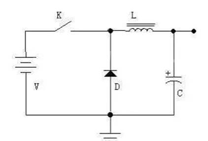
When the switch is closed, the power source supplies power to the load through the switch (K) and the inductor (L), and stores some of the energy in the inductor (L) and the capacitor (C). Due to the self-inductance of the inductor (L), the current increases relatively slowly after the switch is turned on, which means that the output voltage does not immediately reach the power source voltage. After a certain period of time, the switch opens. Due to the self-inductance of the inductor (L) (which can be thought of as the inertia of the current in the inductor), the current in the circuit remains constant, flowing from left to right. This current flows through the load, returns through the ground line, reaches the positive terminal of the freewheeling diode (D), passes through the diode (D), and returns to the left terminal of the inductor (L), thus forming a loop. By controlling the on and off times of the switch (using pulse width modulation or PWM), the output voltage can be controlled. If the on and off times are controlled based on the detected output voltage to maintain a constant output voltage, voltage regulation is achieved.
During the switch on period, the inductor stores energy, while during the switch off period, the inductor releases energy. That’s why the inductor (L) is called an energy storage inductor. The freewheeling diode (D) provides a current path for the inductor (L) during the switch off period, hence it is called a freewheeling diode.
In practical switch-mode power supplies, the switch (K) is replaced by a transistor or a field-effect transistor. When the switch is open, the current is very small, and when the switch is closed, the voltage is very small, resulting in low power dissipation (U×I). This is the reason for the high efficiency of switch-mode power supplies.
