
Shunlongwei Co. ltd.
IGBT Module / LCD Display Distributor
Customer Service
+86-755-8273 2562
IGBT Module / LCD Display Distributor
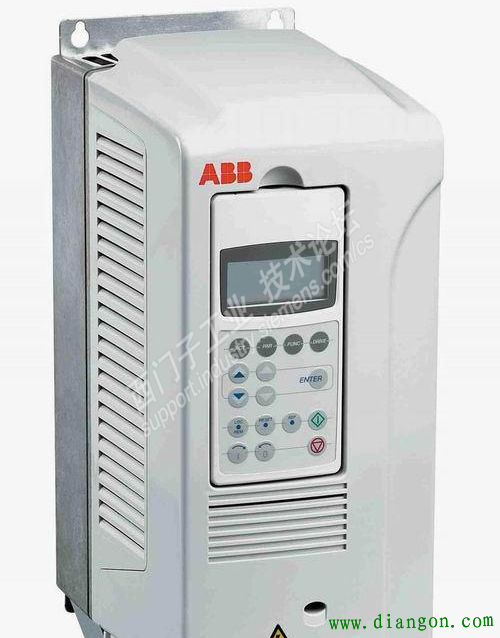
In this case, the customer’s requirement is to connect the ABB inverter to the Profinet network. The equipment used is Siemens 1200 plc, ABB inverter and Xiaojiang Intelligent Control Modbus to Profinet gateway.
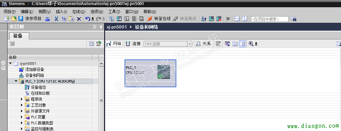
1. First open the Siemens configuration software and create a new project.
2. Stand-alone option-Manage General Station Description File (GSD) to install the GSD file, click Browse to find the location of the GSD file. (Note that it is the folder location, not the file itself).
3. Select the order number of Modbus to profinet gateway.
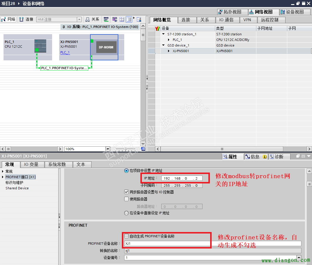
4. Set the IP address and device name of the Modbus to Peofinet gateway. (To be consistent with the gateway configuration software).
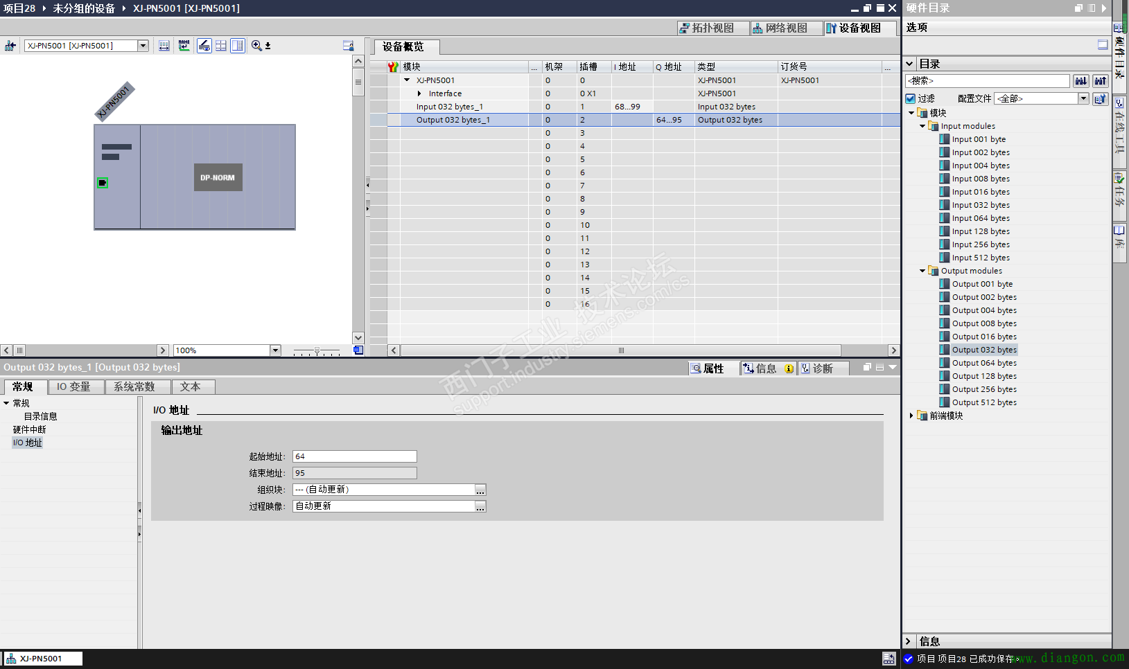
5. Set the total data volume of parameters for reading and writing (changes according to the actual situation).
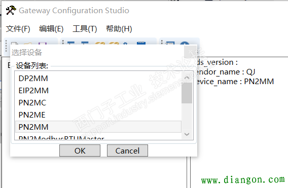
6. After the Profinet configuration is completed, download the configuration to the PLC, set the Modbus configuration of the Modbus-to-Peofinet gateway, open the configuration software of the Modbus-to-Peofinet gateway, and select PN2MM for the new project.
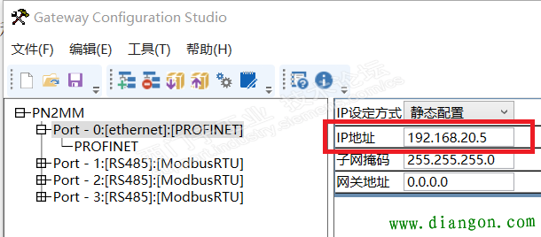
7. First select Port-0 to set the IP address and device name of the gateway (to be consistent with the Botu configuration), refer to the IP address PROFINET device name in Figure 3.
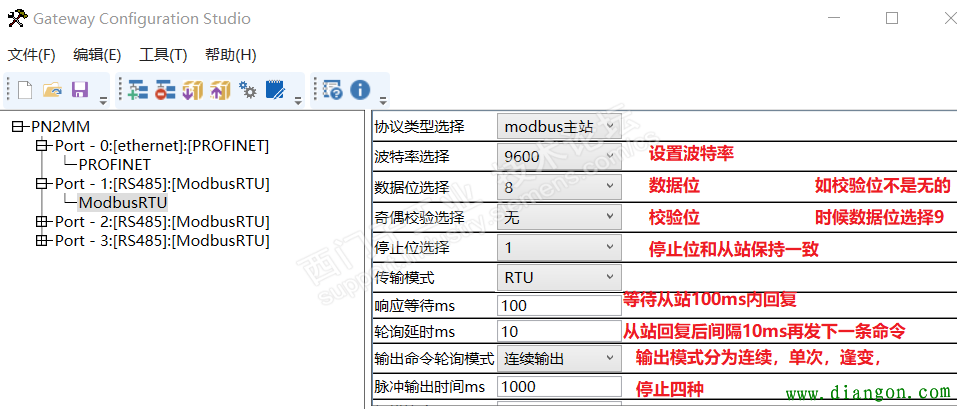
8. Set the 485 parameters of Modbus to Peofinet gateway
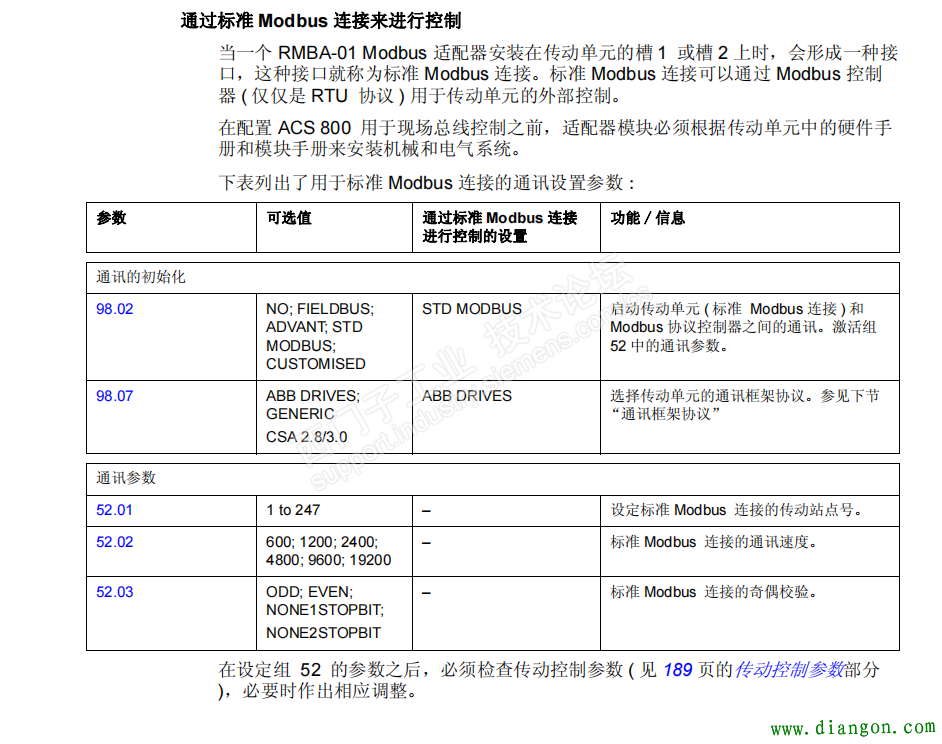
9. Open the ABB instruction manual, configure the 485 parameters of the inverter, and the master and slave stations are consistent
10. Click Insert to add the station number of the slave station
11. Insert Modbus instructions at NODE
12. The specific command function code can be selected according to the Modbus communication manual of the slave station
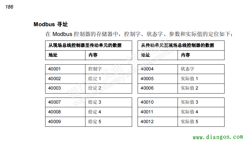
13. As shown in the figure above, if the register address starts with 4XXXX, the read function code is 03. Read the status word, actual value 1 and actual value 2 three register parameters. Then the gateway is set as follows.
Select 03 function code, the gateway start address starts from 0, so if the slave address starts from 1, then the register start address must be reduced by 1, so fill in 3 here. The number of registers is 3, which means reading the data of three consecutive registers starting from the status word, and the mapping start address corresponds to the I address of the PLC.
Byte swap can be divided into
Two-byte exchange = AB-BA
Four-byte register exchange = ABCD-CDBA
Four-byte size end exchange = ABCD-DCBA
Scan mode and command status word usually keep the default
No corresponding action is divided into hold and set to 0 to represent data action after modbus communication timeout
The input function code is divided into 06h function code (write single register) and 10h function code (write multiple registers). The specific selection needs to be determined according to the requirements of the slave station. The above is the actual usage method in the project application.


