Shunlongwei Co. ltd.
IGBT Module / LCD Display Distributor
Customer Service
+86-755-8273 2562
IGBT Module / LCD Display Distributor
1. A single button controls the start and stop of the motor.
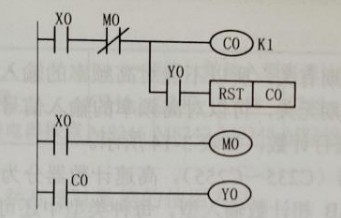
① The counter is used to control the start and stop of the motor. The control Circuit only needs to use a button (X0. When the button X0 is pressed, the coil of the counter CO is energized and counted through the normally closed contact of M0, and the count value is 1 and equal to the set value. 1. The contact of Co acts, the Y0 coil is energized, and the motor is controlled to start. In the first scan cycle, although the Y0 contact is closed, the M0 normally closed contact is disconnected, and C0 will not reset. When the button X0 is released, Y0 continues to be energized.
② When the button X0 is pressed for the first time, the CO coil is energized, but it has reached the set value, so it no longer counts, and the count value is still 1. Because the Y0 contact is closed, the CO is reset, the CO contact is disconnected, and the YO coil is disconnected. Loss of power, the motor stops. In the second scan cycle, the normally closed contact of M0 is disconnected, and the CO coil will not be energized. When the button X0 is released, Y0 will still not be energized. As shown below:
2. Control a disc with PLUC
① The rotation of the disc is controlled by the motor. After pressing the start button, it is required to stop for 3s after every 1 turn, and stop after 5 turns.
② The disc uses a limit switch to detect the number of rotations, and the control ladder diagram is shown in the figure below. The control principle is as follows: in the initial state of the disc, if the start button X0 is pressed when the limit switch X1 is pressed, the YO coil is energized and self-locking, the disc rotates, and the limit switch X1 is reset. The counter CO is reset to 0, M1 is self-locked when it is powered on, and the timer T0 is connected to the circuit.
③ When the disc rotates, when the bump hits and presses down the limit switch X1, the normally closed contact of X1 disconnects the YO coil to release the self-locking, the disc stops, the normally open contact of X1 is closed, and the M0 coil is energized. The MO NO contact is closed in the second scan cycle, ready for the next rotation. The counter CO counts once. When the timer TO is powered on, a pulse is sent out after a delay of 3s, so that the Y0 coil is powered on again and self-locked, and the disc rotates. The disc counts once every turn, when the count value is 5, the normally closed contact of the counter C0 disconnects the Y0 coil, and the whole process ends.
④ In the figure, M1 is used to connect the timer T0 after starting, so as to prevent the automatic delay starting when the original X1 contact is closed.
3. The following describes how to use the high-speed counter.
(1) One-phase one-count input high-speed counter.
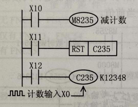
①One-phase one-counting input high-speed counters are numbered C235~C245, with a total of 11 points, and their counting methods and contact actions are the same as ordinary 32-bit counters. When counting up, when the count value reaches the set value, the contact will act and hold; when counting down, it will reset if it is less than the set value. The counting method depends on the corresponding special auxiliary relays M8235~M8245.
②The figure below shows a high-speed counter with one phase and one count input. The C235 in the figure below (a) has only one counting input X0. When X12 is closed, the M8235 is powered on, and the C235 is in the down-counting mode, otherwise it is in the up-counting mode. When X12 is closed, C235 counts the pulses of the counting input X0, which is the same as the 32-bit internal counter. In the counting mode, when the count value is greater than or equal to the set value, the C235 contact will act. When X11 is closed, C235 is reset.