
Shunlongwei Co. ltd.
IGBT Module / LCD Display Distributor
Customer Service
+86-755-8273 2562
IGBT Module / LCD Display Distributor
“The finite element method is widely used in the modal, strength and stiffness analysis of mechanical structures because of its high computational accuracy, especially in the linear range of material stress-strain.
“
The finite element method is widely used in the modal, strength and stiffness analysis of mechanical structures because of its high computational accuracy, especially in the linear range of material stress-strain.
By establishing high-performance computer-aided engineering analysis systems, OEMs and automotive design companies have widely carried out CAE applications simultaneously with product development by their professional CAE teams, playing an increasingly significant role in guiding design, improving quality, reducing development costs and shortening development cycles. effect.

The mature aspects of CAE used in car body development mainly include: mode, stiffness, strength, NVH analysis, mechanism motion analysis, etc.; and the accuracy of vehicle crash simulation analysis, sheet metal stamping forming simulation analysis, fatigue analysis and aerodynamic analysis It has been further improved and has been put into practical use, which can be used for qualitative analysis and design improvement.
Not long ago, the author originally launched the modal stiffness and strength co-simulation of the entire vehicle structure on the simulation show platform. It uses Hypermesh software as a finite element preprocessing tool and Nastran software as a modal, stiffness, strength and vibration analysis simulation tool. Femfat software, as a battery pack vibration fatigue simulation tool, establishes a finite element simulation analysis model, and finally uses Hyperview software to view and evaluate the working conditions results of auto parts modal, stiffness, strength and vibration fatigue. The course is explained in detail and helpful. In this way, scholars can quickly grasp the key points of finite element learning. I would like to take this opportunity to share with you the process and cases of the joint simulation of the modal stiffness and strength of the vehicle structure.
1. Geometric cleanup
Use Hypermesh software to preprocess the model:
For the simulation of structural rigidity and strength, the components in the model that have little influence on the system can be discarded; the geometric features of parts that have a greater influence on the system can be simplified appropriately, such as chamfering structure, structure alignment, etc. After the simplification is completed, check the entire model for interference and other problems. If there is any problem, use the Hypermesh software to repair it. If there is no problem, use the mid-surface extraction tool to extract the mid-surface of the model. After the middle surface is extracted, geometric cleaning is performed:
1. For sensitive parts such as the periphery of the bolt hole and the chamfer, the side length of the unit is not less than 3mm, the number of units between 3-5mm is less than 3% of the total number of units, the average size of the solid unit is 3mm (2-4mm), and the hexahedral unit is used.
2. Unit quality

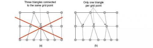
The number of triangular elements in the entire model is less than or equal to 15%. Except for structural restrictions, no more than two adjacent triangular elements are allowed;
3. The mounting holes below R4 are simulated with 4 nodes, and at least 6 nodes above R4;


4. The chamfering below R5 is ignored, and it is represented by one layer of units; the width is greater than 8mm, and it is represented by two or more layers of units;

5. The solder joints are established with connectors, and include the information of each layer of soldering, and there are at least 2 rows of units on the soldering side;
6. The node projections of each layer of the solder joint are aligned, and the solder joint type is acm;
7. The welding seam is connected by rbe2 unit, and the upper and lower layers are two layers;
8. The chassis sheet metal parts are modeled with 5*5 SHELL, and the element nodes are aligned;
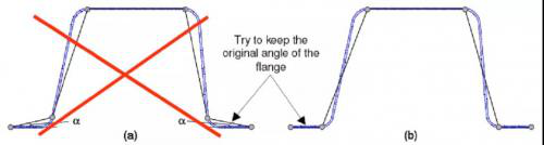
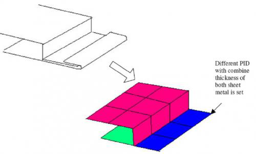
9. Edge wrapping: The initial connection between the outsourcing part and the wrapped part has a common node, and the edge wrapping has only the middle layer of units;

10. Bolted connections: RBE2 and BAR elements co-simulated / or just rbe2
11. Glue: the upper and lower elements are aligned with the connecting parts nodes, and the solid elements are used to adhensive
13. The concentrated mass adopts MASS particles;
14. Contact thickness (interference check)
15. Each part should be checked for normal direction and free edge, the normal direction is the same, and there can be no free edge;
16. The buckles of the instrument panel and the interior of the closure are simulated by RBE2.
After the above processing, an unconnected finite element model can be obtained. At this time, each component in the model exists independently, and the connection relationship has not been resumed, as shown in the following figure:

2. Model assembly connection
By analyzing the structural composition of the digital model and the function of each component, the retention, simplification, and connection relationship of the components are determined. Under the condition of ensuring the simulation accuracy as much as possible, the number of meshes is reduced through simplification and the quality of the mesh is improved. However, the connection relationship between components can have a great effect and influence on the simulation results, so it is necessary to accurately set the connection of the model. The image below is the connected model. Common connections include solder joints, glue, seam welds, and bolts.

3. Finite element boundary condition setting
In order to make the simulation results more reasonable, the finite element model must establish scientific boundary conditions. There are mainly the following boundary conditions: constraints (single-point constraint SPC, multi-point constraint MPC), etc., loads (concentrated force, uniform force, moment), etc.

4. Simulation Analysis
Using Nastran software as a simulation tool for modal, stiffness, strength and vibration analysis, and using Femfat software as a battery pack vibration fatigue simulation tool, a finite element simulation analysis model was established. Finally, Hyperview software was used to realize the analysis of the modal, stiffness, and strength of automobile parts. View the analysis results of working conditions such as vibration and fatigue.
5. Screenshots of the case
1. Front suspension constraint mode (as shown below):

2. Free modal analysis of body-in-white (as shown below):

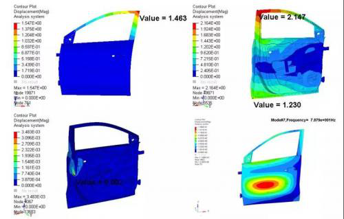
3. Door constraint modal analysis Door torsion, window frame and mounting point stiffness analysis (as shown below)
4. The body-in-white stiffness analysis includes stiffness curve drawing (as shown below)

5. Strength analysis of hydraulic table (gravity field) (as shown below)

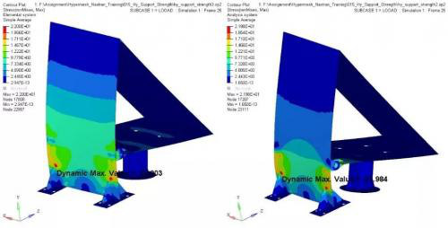
6. Strength analysis of hydraulic drag support (concentrated force) (as shown below)
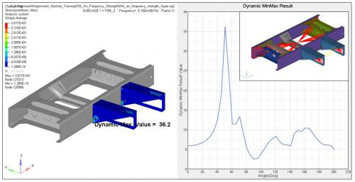
7. Analysis of frequency response intensity of heavy truck air conditioner bracket (frequency response intensity) (as shown below)
8. Strength analysis of the lower arm (inertia release) (as shown below)

9. Random vibration analysis of power battery pack and vibration fatigue analysis of power battery pack (vibration fatigue) (as shown below)

10. Front suspension transient response analysis and front longitudinal beam buckling analysis (transient response and buckling analysis) (as shown below)

The Links: LM190E05-SL02 ADV7612BSWZ


