The drive circuit of the IGBT must have two functions: one is to achieve electrical isolation between the control circuit and the gate of the driven IGBT; the other is to provide a suitable gate drive pulse. There are many driving circuits for IGBTs, and the driving circuit for discrete components is simple and inexpensive. The dedicated integrated driving circuit has perfect protection functions and stable performance, but the price is slightly more expensive.
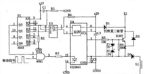
EXB841 is a hybrid integrated circuit produced by Fujifilm of Japan. It can drive 600V IGBTs up to 400A and 1200V IGBTs up to 300A. The module has perfect functions, single power supply, positive and negative bias, overcurrent detection, protection, soft shutdown, etc. The main feature is a typical drive circuit. Powered by +20V DC power supply, it can generate +15V open-gate voltage and -5V off-gate voltage. Built-in TLP550 high-speed optocoupler isolation chip, drive circuit signal delay is less than 1us, internal over-current detection circuit and low-speed over-current cut-off Circuits have been widely used in China. Pay attention to the following aspects when using this module: the gate of the IGBT should be less than 1 m; the gate drive of the IGBT should be twisted pair; if a large voltage pulse is generated at the IGBT collector, the IGBT should be added. The tan-series resistor (RG); the 47uF capacitor is used to absorb voltage variations due to the power supply wiring impedance and is not a capacitor for the power supply filter. The following figure shows the drive and protection circuit consisting of EXB841:
When the IGBT is working normally, the overcurrent signal indicating terminal of EXB841 is high level, 4N25 is not conducting, the trigger R pin is “0”, the Q pin is “1”, and the IGBT works normally. When the IGBT has an overcurrent signal, the EXB841 internal overcurrent detection circuit delays by a few microseconds to filter out the interference signal. The 5 pin becomes low level, 4N25 turns on, the flip-flop flips, and the Q pin is “0”. Turn off the IGBT drive signal for protection. In the work, the special integrated drive module EXB841 was applied, which driven the electromagnetic excitation coil of 2 kw inductive load-high frequency fatigue testing machine.
The driving and protection of IGBTs were analyzed. Combined with practical applications, the following conclusions were drawn:
1. The gate series resistance and the internal impedance of the drive circuit have a great influence on the turn-on process of the IGBT and the waveform of the drive pulse. The design should be considered together.
2. Under large inductive loads, the switching time of the IGBT should not be too short to limit the peak voltage formed by di/dt to ensure the safety of the IGBT.
3. Since IGBTs are mostly used in high voltage applications in power electronics, the drive circuit and control circuit should be strictly isolated at the potential, and the connection between the drive circuit and the IGBT should be as short as possible.
4. The gate drive circuit of IGBT should be as simple and practical as possible. It is best to have its own protection function for IGBT and strong anti-interference ability.
5. In practical applications, in order to achieve better results, methods such as soft turn-off and falling gate voltage are also required for overcurrent protection; clamp circuits are used to prevent surge voltages.