Content last revised on October 14, 2026
Assembly Integrity & Layout Architecture: Industrial Surge Protection for VHF36-12IO5
With the incoming supply isolated and stored energy discharged, trace the power terminals against the equipment schematic before disconnecting the VHF36-12IO5. Record conductor positions, protective-device markings, and the mounting arrangement so that subsequent checks distinguish a module fault from a wiring or protection-coordination problem.
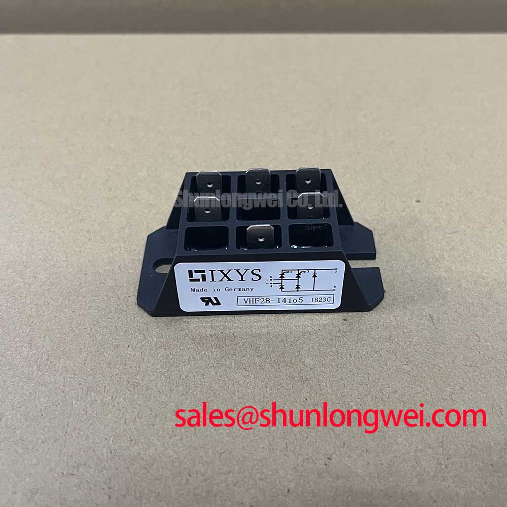
The IXYS VHF36-12IO5 is a bridge rectifier module with a 1200 V voltage rating, 36 A current rating under the specified datasheet conditions, and VUO/VUB Case package designation. For replacement assessment, consult the manufacturer’s datasheet for the internal circuit, terminal assignments, rating conditions, mounting torque, and transient withstand limits.
Locate the surge diversion path before selecting an MOV or changing the input wiring. As a Design Consideration, the protective device should divert incoming transient energy without routing its discharge current through sensitive control returns or unnecessarily long module connections. Assess the protective voltage at the module terminals, including the contribution of connection inductance, rather than relying only on an MOV’s nominal designation.
The relevant surge immunity reference is IEC 61000-4-5, not IEEE 61000-4-5. It describes equipment-level testing; the module’s voltage rating does not establish compliance. The equipment designer determines the applicable test conditions and acceptance criteria, then verifies the assembled protection network under those conditions.
Inspect terminal barriers, cable lugs, and adjacent conductive hardware for clearance restrictions introduced during repair. Creepage and clearance assessment depends on the equipment’s insulation coordination, working voltage, pollution conditions, and applicable standard. The package designation alone does not establish acceptable external spacing. Keep protective-earth connections and power conductors mechanically secure without allowing cable strain to load the module terminals.
For mounting, use the specified fastener arrangement and torque associated with the actual package drawing. Check the heatsink contact surface and interface material before tightening; increasing torque is not a remedy for poor surface contact. As an Engineering Recommendation, document the mounting condition alongside the electrical inspection so that thermal and connection faults remain traceable.
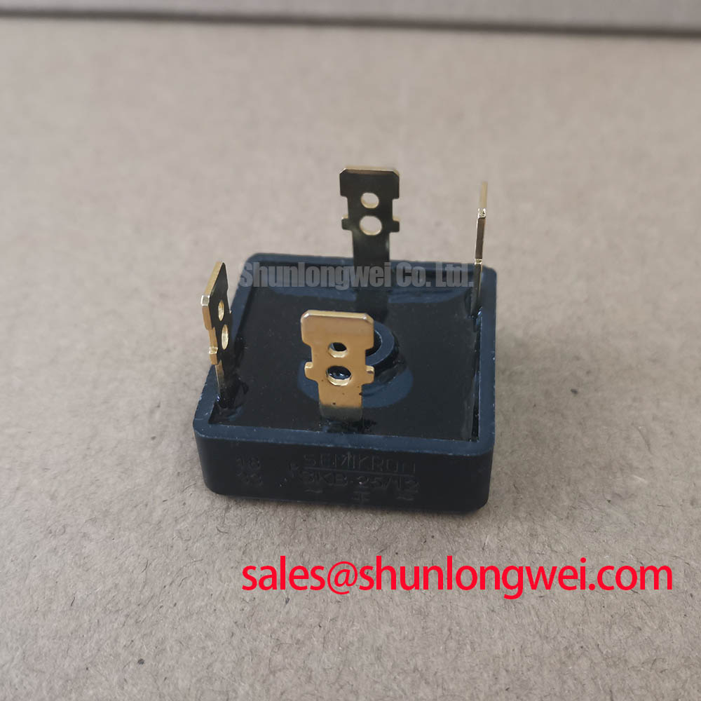
When comparing the SKB 30/12 A1, assess circuit configuration, terminal mapping, thermal limits, dimensions, and protection requirements independently. Treat it as a comparison candidate, not an established direct replacement based on voltage class or product naming.
Benchtop Waveform Tuning: RC Snubber Optimization Around VHF36-12IO5
Capture the voltage across the relevant power junction and the corresponding branch current during representative switching events before modifying an RC snubber. As a Design Consideration, distinguish repetitive commutation ringing from supply surges: an RC network and an input surge suppressor address different stress mechanisms.
For thyristor-controlled branches in the equipment circuit, assess off-state voltage slew and current rise at turn-on against the applicable device limits. Snubber capacitance influences transient voltage behavior, while resistance affects damping and capacitor discharge current. Select both through circuit analysis and waveform validation, including resistor pulse loading and capacitor voltage stress, rather than assigning universal component values.
A series saturable reactor also requires system-level assessment. Its behavior depends on the current waveform, magnetic reset, and operating conditions; it should not be added as an assumed cure for unexplained switching failures. Confirm that any modification does not impair commutation or introduce unacceptable heating elsewhere in the power path.
Practical tip: Keep the snubber connection loop compact and validate the waveform at the module terminals, because a clean trace elsewhere can conceal local overshoot.
When reviewing trigger supplies and isolation circuitry, separate power-path transients from control-side interference. As a Design Consideration, evaluate an isolator’s common-mode transient immunity against measured disturbances and inspect its return-current routing. IGBT Miller-clamp practices should not be transferred indiscriminately to thyristor trigger circuits. If the schematic also references VHF28-16IO5, assess its documented role and connections separately rather than assuming identical drive or protection requirements.
VHF36-12IO5 Circuit Protection & Reliability: Semiconductor Fuse Coordination
Compare the fuse’s total clearing I²t with the protected semiconductor’s applicable withstand data at the relevant voltage, fault conditions, and initial temperature. As a Design Consideration, current rating alone cannot establish coordination, and a pre-arcing I²t figure should not be mistaken for total clearing I²t.
The coordination record should identify the prospective fault current, fuse interrupting capability, clearing characteristics, semiconductor surge limits, and operating conditions used for comparison. Include repeated starting duty and enclosure heating when checking whether normal operation could fatigue or nuisance-operate the fuse. These checks support protection selection; they cannot guarantee damage-free interruption of every short circuit.
The distinction between general circuit protection and rapid semiconductor protection is discussed in Semiconductor Fuse (High-Speed Fuse) Protection. Use manufacturer coordination data for the actual devices, with the Power Semiconductor Selection Guide supporting the broader comparison workflow.
When evaluating this module for a high-voltage three-phase motor solid-state soft starter, establish its exact rectifier role from the equipment schematic before approving compatibility. After a protection event, check connected power branches, trigger circuitry, terminal condition, and the heatsink interface before controlled recommissioning; replacing the operated fuse alone does not establish that the fault has cleared.