Shunlongwei Co. ltd.
IGBT Module / LCD Display Distributor
Customer Service
+86-755-8273 2562
IGBT Module / LCD Display Distributor
“The specification of the onboard DC-DC converter is an important and detailed process. When properly sized, it results in a cost-effective solution for all applications. Wrong choice of converter can result in cost prohibitive or unsuitable for the application. This FAQ will cover the main specifications of the onboard DC/DC converter, including thermal management and electromagnetic compatibility considerations.
“
Specifications of DC/DC Converters
The specification of the onboard DC-DC converter is an important and detailed process. When properly sized, it results in a cost-effective solution for all applications. Wrong choice of converter can result in cost prohibitive or unsuitable for the application. This FAQ will cover the main specifications of the onboard DC/DC converter, including thermal management and electromagnetic compatibility considerations.

This 96% efficient 40A point of load (PoL) non-isolated board mount DC/DC converter measures 33mm x 13.5mm x 10.2mm. (Image: TDK)
Efficiency is often the most important specification for a DC/DC converter, and it has a major impact on many aspects of system design. Even in high-efficiency designs, improvements in efficiency can have a significant impact. A design with 95% efficiency has 5% heat loss, and a DC/DC converter with 80% efficiency has 20% heat loss, a difference of four times. This difference affects many aspects of system design:
The operating temperature can be reduced, or the system power density can be increased at the same operating temperature
Physical size reduction of the system
Lower system cost as smaller or even no heat sink can be used
Greatly improved reliability
For AC power systems, front-end AC/DC power supplies will be smaller and less expensive
Battery powered systems can run longer with a smaller battery or at a given power level
Energy costs and environmental impact on the system will be reduced

Efficiency curves of DC/DC converters with 5V DC/1A output at various input voltages. Image: RECOM
Efficiency can be expressed in many ways, such as typical (very common) at various input voltage levels, various output power levels, etc., guaranteed minimum. Also, efficiency is generally not flat over the range considered. For output power versus efficiency, it is important to consider the shape of the efficiency curve and match it to the expected operating state of the system to maximize efficiency under actual operating conditions.
In many applications, especially battery-operated equipment, no-load power consumption can be an important indicator, which is related to the power dissipation of the switching circuit and is the limiting factor for overall efficiency.
output regulation
The rated output current is a straightforward specification. Some DC/DC converters also specify a minimum load. Depending on the converter, operating below minimum load can negatively affect voltage regulation, but not damage the converter. The output voltage is a more complex parameter to specify. The two factors that provide a starting point for specifying the output voltage are the nominal value, or “set point,” and the relationship between that nominal value and various independent parameters (such as changes in output load, changes in input voltage, and changes in operating temperature.)
An example of a setpoint specification is ±1% at rated input voltage, full load and 25°C. Line and load regulation is usually specified as a percentage or absolute range, eg, ±0.1% or ±5mV. Temperature regulation is usually specified “per degree Celsius”, such as ±0.01%/°C or parts per million (PPM), as indicated in PPM/°C. Some DC/DC converter suppliers provide a single specification for “total regulation” of all possible variations, rather than the individual specifications outlined above. For voltages below 3V, it may be more important to specify the output voltage regulation in detail.
In typical applications, the line input voltage and operating temperature change relatively little during system operation compared to the output load level. As a result, load regulation is a more critical specification. Additionally, dynamic voltage regulation (sometimes called transient response) occurs due to changes in the step function in the output load.
Dynamic adjustment
For many systems, dynamic regulation is more critical than static voltage regulation. When specifying dynamic regulation, it is necessary to quantify the absolute change in load, the rate of change, the definition of “recovery”, and the time to achieve recovery. For example: “Load change of 25% to 75%, dI/dt is 0.1A/µs, maximum deviation is 3%, and returns to 1% of set value in 200ms.” The output voltage will decrease as the current increases , and increases as the current decreases.

The output voltage is dynamically adjusted, and the transient response deviation and recovery time are displayed. (Image: Keysight Technologies)
Dynamic response is both a system design consideration and a power supply design consideration. The impedance and decoupling design of the power distribution network has a significant impact on dynamic regulation. Dynamic scaling is especially important when powering large digital ICs such as FPGAs and microprocessors for board-mounted DC/DC converters.
The output of a switching DC/DC converter contains both low-frequency (ripple) and high-frequency (noise) components, typically expressed as 0 to 20 or 50 MHz peak-to-peak. Typical specifications for ripple and noise are 75mV peak-to-peak for a 5V output. The frequency of the ripple is related to the switching frequency of the converter. Noise is more variable and is caused by the high dI/dt parasitic inductance ringing inherent in the operation of switch-mode converters. Noise pops up during switching transitions and is superimposed on the lower frequency ripple. Electromagnetic compatibility requires detailed consideration when using the on-board DC/DC converter.
Protective function
Overcurrent protection is designed to protect the converter from system faults such as short circuits. There are three common ways to implement current limit protection, maximum current limit, foldback current limit and hiccup current limit. In the maximum current limit, the load current is limited within a range that does not exceed the maximum value. When this value is reached, the output voltage drops. During the current limiting phase, the power dissipation in the DC/DC converter is usually higher than in normal operation. Foldback current limit reduces output current when a fault is detected. This enables lower maximum power dissipation compared to the maximum current limit. However, the foldback current limit may provide less current at startup. As a result, if the load current during startup is greater than what is supported by the foldback current limit, the output will rise more slowly, or the converter may fail to start.
When the current detection circuit detects an overcurrent condition in the hiccup current limit, the DC/DC converter will shut down for a period of time and then try to start again. If the overload condition is removed, the converter will start and operate normally; otherwise, the controller will consider another overcurrent condition and shut down, repeating the cycle. Hiccup operation eliminates the shortcomings of the other two overcurrent protection methods. However, it is more complicated due to the need for timing circuits.

Hiccup current limit is more complex than maximum current limit or foldback current limit. Converters with hiccup protection make a “tick” sound every time they try to reboot. Image: RECOM
Typically, output overvoltage conditions caused by converter faults are clamped to a certain level. Devices typically fail in a shorted state, preventing damage to the host system. Some DC/DC converters also have an undervoltage lockout feature that shuts them down at low input voltages. The converter operates in “power-down mode,” in which the output power is limited to prevent excessive input current from flowing in.
General Specifications
In specific applications, many additional specifications may be important, such as PMBus communication capabilities for converter configuration and monitoring. The remote switch function can control the power-up and power-down sequence of multiple converters or select remote for safety reasons, and the telemetry function may be important for some applications.
Most board mounted DC/DC converters are non-isolated buck converters. However, sometimes an isolated converter is required and the level of isolation voltage needs to be specified. Isolation capacitance is also important, mainly the parasitic coupling between the primary and secondary windings of the transformer in isolated converters.
2. EMC and EMI
Electromagnetic compatibility (EMC) and electromagnetic interference (EMI) are system-level considerations that affect power system design, especially when multiple on-board DC/DC converters are used in a distributed power architecture (DPA). EMC/EMI is a multifaceted consideration that includes differential and common mode noise at the input and output of the converter, radiated and conducted noise, and the susceptibility and emission levels of the converter.
EMC is defined as the ability of equipment to operate as specified even when subjected to various forms of EMI within a given range. Board mounted DC/DC converters can be large sources of EMI that must be controlled to ensure proper system operation. And it’s also susceptible to interference, especially on the input side.
High-frequency board-mounted DC/DC converters need to be selected to minimize the size of the magnetic components in the converter, thereby reducing the overall solution size. Using smaller passive components makes it easier to design compact circuits, resulting in better EMC/EMI characteristics.
However, high frequencies can also lead to increased EMI in the power switching circuits in the converter. One of the reasons is that steep MOSFET switching edges result in higher dI/dt (depending on rise time, which is up to several hundred MHz), which is affected by MOSFET output capacitance, junction capacitance, reverse recovery capacitance of Schottky diodes, etc. .
EMC/EMI
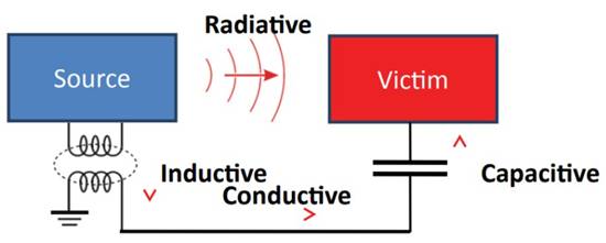
EMI coupling mechanism (Image credit: Boyd Corp.)
As mentioned above, EMI can come in the form of conducted, radiated or coupled emissions. Depending on the application and system design, each type of EMI generation can become a significant issue when using multiple board-mounted step-down DC/DC converters in a DPA.
Conducted emissions are harmful electromagnetic energy introduced into Electronic systems through wires, circuit board traces, etc. It can take the form of common mode or differential mode (also known as normal mode) energy.
Coupled emissions include capacitive or inductive coupling of electromagnetic energy from an interference source to an electronic system.
Radiated emissions are electromagnetic energy radiated throughout space from the source of interference to the electronic system.
EMI standard
There are two types of EMC standards, basic and generic/product related. Like IEC 61000-4 and CISPR 16, basic EMC standards do not specify emission limits or immunity test levels. They specify how to perform measurements. Common EMC standards and product (family) EMC standards (such as CISPR/EN 55022/32 and FCC) specify limits and test levels, see Basic EMC publications for test setup and method specifications.
Designers of IT and multimedia equipment must use quasi-peak and average signal detectors in the applicable 150kHz to 30MHz frequency range to meet EN 55022/32 Class A and Class B limits for conducted emissions. Both quasi-peak and mean limits must be met. Products designed for the North American market must comply with the equivalent limits set forth in FCC 15. Conducted emission limits for Class B settings are the same as those in CISPR 22 and EN 55022/32.

CISPR/EN 55022/32 Class A and B Quasi-Peak (QP) and Average (AVG) Conducted Emission Limits (Image: Texas Instruments)
The IEC 61000 basic EMC standard consists of several parts. General (61000-1), Environmental (61000-2), Limits (61000-3), Test and Measurement Techniques (61000-4), Installation Guide (61000-5), Common Criteria (61000-6), Other ( 61000-9).
The CISPR 16 basic EMC standard consists of four parts: CISPR 16-1 has six subparts and specifies voltage, current and field measurement equipment and test locations. These include calibration and verification of measuring equipment. CISPR 16-2 has five subsections that specify methods for measuring high-frequency EMC phenomena, coping with interference and immunity. CISPR 16-3 is an IEC Technical Report (TR) that contains specific technical reports and information about the history of CISPR. CISPR 16-4 includes five subsections containing information related to uncertainty, statistics, and limit modeling.

Summary of major non-military generic/product standards for conducted EMI (Image: Texas Instruments)
contain EMI
Controlling EMI is important for two reasons: Systems that do not meet the above EMI standards are banned in many markets, and too much EMI can degrade system performance. EMI is a multidimensional problem, and there are several ways to control EMI. Radiated emissions and coupled emissions are generally not a problem if board mounted DC/DC converters from reliable suppliers are used. However, the input of the converter needs to be connected to the power bus to minimize the conducted emissions of the converter, and to deal with the possibility that transient susceptibility to the power bus may affect the performance of the converter. Some general considerations include:
Circuit Design: Keep current loops small to minimize the ability of conductors to couple energy through induction or radiation, and design appropriate capacitors and other components in the design to minimize coupling. Additionally, using a board-mounted DC/DC converter that combines frequency spreading with switching frequency dithering can effectively reduce EMI by allowing emissions to remain at any one frequency for any significant period of time.

Six-sided shielded 60W isolated DC/DC converter in a 2x 2 board package. Image: RECOM
Filter: Place the filter as close to the converter as possible. Bypass capacitor leads should be as short as possible. In a typical board mounted step-down DC/DC converter application, input filtering is often the most critical. There is an inductance between the power MOSFET and the output, mitigating EMI at least somewhat. However, EMI on the input side will propagate throughout the system as it will be carried by the main power bus. Although the input side is the most critical, it is not wise to ignore the output side when considering EMI. For board-mounted DC/DC converter suppliers, the external components required to meet specific EMC/EMI standards are usually listed in the datasheet.
Shielding: There is a rule of thumb, when the frequency is below 200MHz, grounding may be a viable solution, but when the frequency is above 200MHz, it will radiate and the best solution is shielding. For applications such as telecommunications, process control, broadcast, industrial, and test and measurement equipment, board-mounted DC/DC converters with six-sided metal shielding are often recommended to maximize EMC/EMI performance.
At the end of the day, EMC/EMI is a system level issue. Optimizing the EMC/EMI performance of the onboard DC/DC converter is an important consideration, but other system elements are often more critical to EMC/EMI performance.
3. Thermal management and thermal analysis
System-level thermal design is equally important to the electrical specification of a DC/DC converter. The increasing use of distributed power architectures (DPAs) increases the complexity of thermal design. A single multiple output AC/DC power supply is used to power various loads in conventional power supply architectures. The use of a centralized power supply concentrates the heat dissipation during the power conversion process, thus enabling a direct heat dissipation design.
In a DPA, a single output AC/DC power supply generates a relatively high distribution voltage (such as 12VDC or 48VDC) and powers a low voltage load through multiple non-isolated step-down DC/DC converters. The DPA architecture spreads the cooling of the power conversion process throughout the system and complicates the cooling design. The benefits of using DPA can include smaller overall solution size, higher efficiency and lower cost.
DC/DC Converter Selection Considerations
Efficiency is often considered the most important specification. Efficiency has a major impact on thermal management. Therefore, it is very important to use an efficient DC/DC converter. But it’s not that simple. Efficiency is usually specified at full load, and DC/DC converters are often derated and operated below full power to improve system reliability. And the system usually doesn’t run at maximum power all the time. It turns out that choosing the most efficient converter for a given application is not as simple as it first seems. Once the system operating conditions are known, the designer can select a DC/DC converter whose efficiency characteristics match the system requirements.
Additionally, buck converters used in DPAs come in a variety of designs, each with different efficiency tradeoffs. For example, at high loads, a synchronous buck converter is more efficient than a non-synchronous buck converter. But the best choice depends on the operating characteristics of the system. Asynchronous bucks are generally more efficient at light loads than synchronous designs. In systems that operate at low power levels for a significant amount of time and only occasionally require peak power, a non-synchronous buck can provide higher overall operating efficiency. Asynchronous bucks are less expensive and more reliable due to their simpler design.

Efficiency comparison of synchronous and asynchronous DC/DC converters rated at 12V input and 1.5V output. Image: Texas Instruments
In systems requiring the highest efficiency, the use of emerging semiconductor materials such as gallium nitride (GaN) can provide higher efficiency and smaller size. GaN is a wide-bandgap material with higher conductivity than conventional silicon. Compared to silicon devices, GaN transistors are smaller and have lower capacitance with the same on-resistance. Zero QRR reduces high frequency losses. The switching performance of GaN enables higher power density, higher frequency, higher switching accuracy, higher bus voltage and less voltage conversion losses.

Efficiency comparison of silicon to gallium nitride (GaN) 48V to 12V DC/DC converters. (Image: EPC)
Not all board mounted DC/DC converters are the same when it comes to thermal design and cooling capabilities. Some are built on insulated metal substrates for enhanced thermal performance. Some include thermal vias for improved thermal conductivity, and others are starting to use 3D packaging, which uses stacked, embedded or planar components to significantly reduce size.
Reducing the physical size not only increases power density, but also reduces parasitics and smaller current loops, which means that EMI can be kept under control even with MHz switching frequencies. The trade-offs make thermal management potentially more complex. The overall temperature performance of a DC-DC converter is highly dependent on the end application.

As performance increases in increasingly constrained board spaces, technological advancements such as 3D power packaging are required to ensure that power consumption does not increase rapidly. Otherwise, the performance limit will depend on temperature, not maximum power designed. Image: RECOM
System heat distribution
Thermal management begins with the identification of hot spots and other areas of focus during the design phase by measuring operating temperature through a system heat map. For a specific operating environment, heat maps are necessary to achieve proper thermal management system design. It helps to identify areas that need to be monitored (measured) during system operation.
If thermal imaging using an infrared (IR) camera shows that one or more of the hotspot PCBs are hotter than expected, this may indicate a problem. It is important to consider components in close proximity to higher heat; they may experience long-term aging effects. In order to detect hot spots, sufficient geometric resolution is required. Details that are well resolved and measured correctly are only possible with a sufficient number of pixels. Therefore, a high-resolution infrared camera system is a good choice for use during system development.

During product development, high-resolution infrared camera systems are often used for thermal imaging. Image: InfraTec
Unlike thermocouples or spot pyrometers, high-resolution thermal imaging cameras can obtain accurate temperature readings on systems and equipment. And the thermal design is not static. Under changing system operating conditions, overall system cooling typically changes (sometimes rapidly). Some thermal imaging cameras can record high-speed data with the sensitivity and spatial resolution required to characterize fast thermal transients and steady-state thermal conditions.
Monitor thermal performance
Built-in thermal shutdown is often used in board mounted DC/DC converters, and it is often useful to continuously monitor the converter’s operating temperature. Below are two examples of components that can be used for thermal monitoring.
Thermistors are resistances that change with temperature and are usually made of conductive materials such as metal oxide ceramics or polymers. The most common thermistors have a negative temperature coefficient of resistance (NTC) and are often referred to as NTC. Using NTC requires signal conditioning. Thermistors are often used with fixed-value resistors in a voltage divider, the output of which is digitized using an analog-to-digital converter (ADC).

A basic circuit showing how a thermistor interfaces with an ADC. Resistor R1 and the thermistor form a voltage divider whose output voltage depends on temperature. (Image: Maxim)
The temperature sensor IC utilizes the thermal characteristics of the PN junction. Since they are active circuits built using conventional semiconductor processes, they can take many forms and have multiple functions (such as digital interfaces, ADC inputs, and fan control functions). Temperature sensor ICs operate from -55°C to +125°C, with some devices operating up to about +150°C.
4. Failure rate and reliability
The reliability of the onboard DC/DC converter is important to understand and quantify. It is a measure of the frequency of system or equipment failures over time. Reliability is the observed failure rate, which is defined as the time (in hours) between failures, known as the mean time between failures (MTBF), or the time until the first failure (also in hours) units), known as mean time between failures (MTTF). Sometimes reliability is quantified by the inverse of the MTBF number (based on 109 hours), called the Time to Failure Unit (FIT): FIT = 109/MTBF.
Every piece of equipment has a failure rate, λ, which is the number of units that fail per unit of time—a failure rate that varies in a predictable manner over the life of the equipment. When plotted as failure rate versus time, it is often referred to as a reliability bathtub curve. It shows the sum of early failure rates, as well as constant (random) failure rates throughout the life of the product, plus end-of-life wear rates.

The bathtub curve is used to illustrate the observed failure rate of the electronic system.Image: Wikipedia
During the first phase of a product’s life, so-called failures occur due to material defects or manufacturing errors (not found in final testing and inspection), so the failure rate keeps dropping and λ drops. Most failures of board-mounted DC/DC converters occur within the first 24 hours of operation.
In electronics, the Arrhenius equation is used to determine the expected lifetime of an operating component at a given temperature. It applies to chemical methods, measures temperature-dependent reaction rates, and observes that reducing temperature by 10°C doubles product reliability. Conversely, increasing the operating temperature will speed up the failure rate of electronic equipment.
The Arrhenius equation is the reason why electronic devices and systems fail. For example, running a freshly fabricated DC/DC converter at full load and high temperature for about 4 hours in an aging chamber can eliminate many of the early failures. Typically 40 or 50°C is used for aging, sometimes further higher temperatures and higher humidity are used. High reliability DC/DC converters typically undergo 24 hour burn-in.
During product and system development, accelerated stress testing systems for Highly Accelerated Life Testing (HALT) and Highly Accelerated Stress Screening (HASS) uncover product design weaknesses. Performing HALT and HASS maximizes laboratory efficiency while reducing costs associated with warranties and recalls, thereby increasing product reliability. HALT and HASS use temperature and vibration stress to eliminate design problems, develop more reliable products and screen out early product failure issues. HALT and HASS determine the operational and damage limits of a product as it is functionally tested and constantly monitored for failure while stress is being applied to the product.

HALT and HASS test chambers are used for product development and product testing. Image: Thermotron
Over the life of most DC/DC converters, they experience a constant failure rate λ in addition to the initial failure rate, and the reliability curve is essentially flat. How long the constant failure rate lasts depends on various factors such as the inherent stress of the application environment, the quality of the components used, the manufacturing quality of the DC/DC converter, and more. Failure rates continue to increase as the product wears out at the end of its useful life.
prediction reliability
The two most commonly used tools for predicting reliability are MIL-HDBK-217 and the Telcordia reliability prediction program SR-332. These and other reliability predictions are based in part on the Arrhenius equation. MIL-HDBK-217 was originally developed by the US military to produce MTBF and MTTF data, while Telcordia SR-332 was developed for the telecommunications industry to produce FIT data. Currently, MIL-HDBK-217 is the most widely used reliability calculation method.
Reliability can be predicted and quantified in several ways using parts count analysis (PCA), part stress analysis (PSA), or through field data attestation. Each of these methods of quantifying reliability has specific uses for power system designers. PCA requires minimal data and is typically used during product development. PCA analysis yields an estimated product failure rate λP based solely on the bill of materials and intended use, allowing the calculation of the MTBF of a product that is still being designed: λP = (ΣNCλC)(1 + 0.2πE)πFπQπL (Formula source: RECOM)
in:
NC = number of parts (per component type)
λC = failure rate for each part taken from the database
πE = application-specific environmental stress factor
πF = mixed function stress c through component interaction
πQ = screening level for standard parts or pre-screened parts
πL = maturity factor is a proven design or a new approach
PCA is calculated for each component used, and an overall reliability prediction is derived by summing all individual predictions.

PCA reliability analysis for simple DC/DC converters. (Table: RECOM)
The MIL-HDBK-217F PSA method provides a constant failure rate model based on curve fitting empirical data obtained from field operations and testing. Like PCA analysis, the PSA model has a constant base failure rate that is determined by environment, temperature, stress, mass, and other factors. But the PSA method assumes no correction for a generally constant failure rate. Although it is broadly applicable to devices such as onboard DC/DC converters, the MIL-HDBK-217 method was originally intended to provide results for parts, not for devices or subsystems.
The main concepts of MIL-HDBK-217 and Telcordia SR-332 are similar, but Telcordia SR-332 also has the ability to combine aging, field and laboratory test data for Bayesian analysis methods. Bayesian inference is a method of statistical inference in which Bayesian is used to update the probability of a hypothesis as more evidence or information becomes available.
System Design Considerations
DC/DC converter failure rate analysis focuses on operating temperature, input voltage and output power to estimate overall stress. Good thermal management is the most important aspect of designing reliable systems using board mounted DC/DC converters. Good thermal management starts with understanding how the efficiency of the converter affects system performance. It’s always a good practice to go with higher limit products. Nominal performance specifications are not always the best choice. Rather than looking at the typical ratings specified, looking at the worst-case ratings, especially for efficiency, is usually a good place to start.

Replacing a linear regulator with a pin-compatible switching regulator such as the one shown above can significantly improve efficiency, reduce heat and help improve reliability. Image: RECOM
Efficiency is typically specified at 25°C, but is common for systems operating at higher temperatures. Losses in power semiconductors and circuit board traces increase as temperatures rise. Copper has a temperature coefficient of +0.393%/°C. If the temperature is 1°C above room temperature, the resistance will increase by 0.393%. Converter efficiency varies with input voltage and decreases with input and nominal voltage.
As a result, thermal imaging during system development is necessary to identify hot spots and other areas of interest. With thermal mapping, the correct thermal management system can be designed for a specific operating environment. It helps to identify areas that need to be monitored (measured) during system operation. Thermal mapping can also identify point heat sources, such as linear regulators, that may need to be replaced with more efficient on-board DC/DC converters (eg, switching regulators).
Although thermal management is a major consideration, the characteristics of the input voltage should not be ignored. Operating under critical high or low lines for extended periods of time reduces reliability, while surges, spikes, and electrostatic discharge (ESD) at the input also reduce product performance and longevity. Using a protection device at the input of the converter can greatly improve the reliability of the system.
The Links: NL8060BC31-27 2MBI200U4H-120-50