

Content last revised on September 14, 2026
Preventing Localized Light Guide Plate Compression Warp on Dark Screen Fields
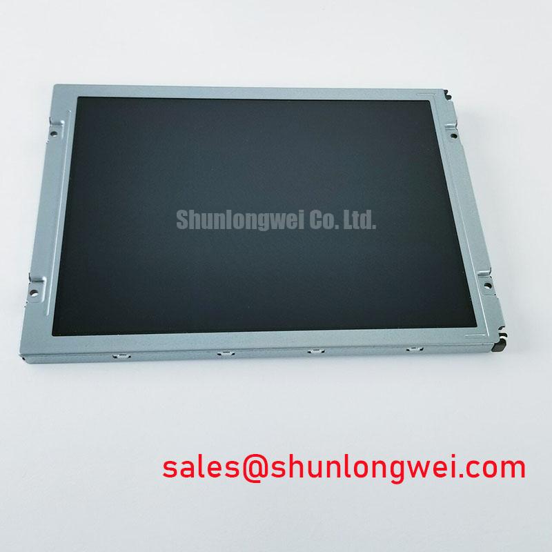
Dark-field inspection should begin before the panel is secured into the CNC operator panel or robot teach pendant. Display a uniform black image, reduce surrounding reflections, and check the screen from the normal operating position as well as from modest off-axis angles. Uneven bright areas, pressure shadows, or localized luminance differences should be mapped against the bezel, mounting holes, gasket contact areas, and rear support points. This record helps separate a display-originated optical issue from stress introduced by the host enclosure.
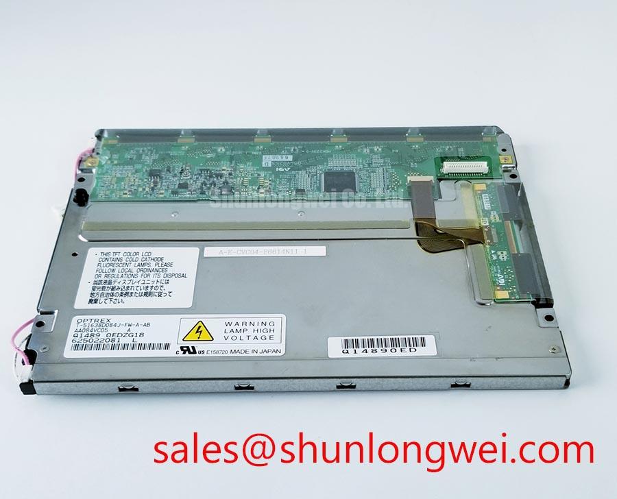
The model is identified as a Mitsubishi Electric TFT LCD display module, but the supplied factory parameter set does not confirm a specific light guide plate construction or optical bonding process. The system integrator should therefore avoid assuming that the module can tolerate direct pressure from a decorative cover, foam strip, bezel, or uneven chassis flange. A mechanical design review should confirm the outer bezel envelope, the free clearance around the active area, and the way the display rests during thermal expansion and contraction.
As a Design Consideration, fasteners should be tightened in a cross-pattern so that the bezel load is released evenly rather than concentrated at one corner. The suggested torque range of 0.35 to 0.45 N·m may be used only as a mechanical starting point when the enclosure uses compatible small fasteners and the original assembly documentation does not specify another value. It is not an official AA084VD02 factory rating. Final torque must be established by the enclosure designer after checking thread material, gasket compression, panel flatness, and dark-field uniformity.
Optical bonding should also be treated as a verified assembly attribute rather than an assumed feature. If the original HMI uses a bonded cover lens, the replacement procedure should confirm whether the existing gasket, frame, and cover geometry are compatible with the module. A sealing layer that is too thick can load the display perimeter, while an incomplete seal may permit dust or moisture to reach the optical stack. For a CNC control cabinet or robot teach pendant, the enclosure should be evaluated for dust ingress, coolant mist, cleaning chemicals, and condensation during cold start.
Backlight ageing should be evaluated against the actual lighting technology used by the original assembly. The available information does not confirm whether this model uses a CCFL or LED backlight, so a maintenance team should not transfer lifetime or half-brightness figures from another panel family. If the system uses a constant-current LED driver, technicians should verify current regulation, enable timing, dimming behavior, and thermal conditions. If the original unit uses a high-voltage inverter, the inverter output and lamp circuit must be checked against the original documentation before connection.
The related AA084VC01 may be reviewed as a same-size or same-resolution reference only after mechanical dimensions, interface signals, mounting geometry, backlight requirements, and display timing have been compared. Similar screen dimensions do not establish drop-in compatibility.
Backlight Inverter Striking Voltage and Ignition Debugging
When a legacy HMI shows a brief flash, delayed illumination, uneven brightness, or an audible tone during startup, begin by separating the panel signal path from the backlight path. Confirm that the host controller is producing a stable image signal, then inspect the backlight enable and brightness control behavior with the equipment isolated from hazardous energy. The AA084VD02 factory information supplied here does not verify a dual-channel CCFL inverter, a cold ignition voltage, an LED driver, or a PWM dimming specification.
For that reason, the suggested values of 1500 to 1650 Vrms for CCFL ignition and 200 Hz to 1 kHz for PWM operation must not be presented as specifications for this model. They belong to a possible troubleshooting framework for a separately documented backlight system. The system integrator should verify the required backlight technology and electrical limits from the original panel documentation before selecting test equipment or applying power.
For a confirmed CCFL assembly, ignition troubleshooting should include the inverter input supply, lamp wiring, transformer condition, connector seating, and protection shutdown behavior. A high-voltage probe rated for the circuit should be used by qualified personnel, with the measurement method selected to avoid disturbing the resonant circuit. A shutdown event can have several possible contributors, including an open lamp path, a driver protection response, connector contamination, or an incompatible replacement inverter. The correct diagnosis requires comparison with a known-good assembly and the documented inverter waveform.
For a confirmed LED assembly, inspect the constant-current driver, enable line, dimming command, and thermal path instead. Flicker or brightness instability may arise from the host controller, driver regulation, grounding, or a mismatch between the display and the control board. Designers should verify duty-cycle linearity and dimming frequency at the system level when visual flicker or acoustic noise is reported. Do not connect a CCFL inverter to an unverified LED panel, or an LED driver to a panel documented for a high-voltage lamp.
Power sequencing deserves the same care as the backlight circuit. The controller should follow the original panel documentation for logic supply order, display enable timing, backlight enable timing, and shutdown behavior. If the screen turns white, retains a ghost image, or illuminates before valid video data is present, capture the supply rails and control signals during startup rather than assigning the symptom to one component. The timing relationship between the host board and AA084VD02 must be confirmed from the actual interface documentation.
⚠️ Maintenance Note: Disconnect power and allow the documented discharge interval before removing the panel cable or opening any backlight inverter compartment.
Shielded FFC and FPC Grounding Across Connector Shells
Pixel jitter, horizontal noise bands, intermittent image loss, and unstable touch or display behavior should be investigated at the complete cable assembly level. Begin with a visual inspection of the FFC or FPC for creasing, incomplete insertion, damaged contacts, and excessive bending near the connector. Check that the cable is not trapped between the display frame and the enclosure, and confirm that any conductive shield or chassis spring makes the intended contact without pressing into sensitive circuit areas.
The supplied factory specification identifies AA084VD02 as a TFT LCD display module but does not provide a confirmed LVDS or TTL pin assignment, clock frequency, data hold time, connector shell construction, or cable shield termination. The system integrator should verify the original panel drawing and controller board schematic before changing the cable. A cable that fits mechanically can still have a different signal order, impedance arrangement, power assignment, or backlight control connection.
As a Design Consideration, shield continuity should be planned around the complete signal path rather than grounded at an arbitrary point. The enclosure, cable shield, connector shell, controller reference, and protective earth arrangement should be reviewed together to reduce common-mode coupling. This is particularly important when the display cable runs near variable-frequency motor drives, contactors, brake resistors, or other high-current switching conductors. Cable routing should minimize parallel exposure to noisy power wiring, while the final arrangement must be verified through conducted and radiated disturbance testing in the completed machine.
Common-mode ferrite components may be considered when the measured noise path has been identified, but their impedance characteristics and placement must match the signal bandwidth. Adding ferrite material without checking the clock and data waveform can increase edge distortion or create a new intermittent fault. An oscilloscope comparison between the controller output and the signal at the panel connector can help identify whether the disturbance is introduced by the host board, cable, connector, or display input stage.
Connector grounding across a shell should not be described as a universal 360-degree requirement for this model because the confirmed AA084VD02 data does not define that construction. Instead, designers should verify how the original assembly handles shield termination and whether the display frame is electrically connected to the machine chassis. The test should include normal operation, motor acceleration, braking, cabinet door movement, and temperature changes that may alter contact pressure or cable position.
If a replacement controller is being evaluated, compare the documented transmitter standard, pixel clock, signal polarity, timing limits, and operating temperature requirements. The absence of a confirmed AA084VD02 interface table means that compatibility must be established from the original equipment records, not from the panel model number alone. The same review applies to a prospective interface reference such as AA084VC01.
Further environmental guidance for enclosure sealing, cable routing, thermal management, and HMI integration is available in the Industrial Display & HMI Solutions engineering resource. It should be used as general integration guidance, while the AA084VD02 documentation remains the authority for model-specific limits.
Full-Screen Primary Color AOI Screening for Stuck Sub-Pixels and Background Uniformity
Incoming inspection should use a controlled display test rather than relying only on a powered logo screen. After confirming that the controller is configured for the original panel, display full-screen white, black, red, green, and blue images. Observe the active area for stuck sub-pixels, vertical or horizontal lines, edge shading, bright points, dark points, and nonuniform background fields. Record the position of any defect so that it can be compared with the same location during a later thermal or mechanical test.
A three-stage bench sequence is practical for maintenance teams. First, inspect a black field in subdued ambient light to expose light leakage, shadowing, and nonuniform backlight behavior. Second, use primary red, green, and blue fields to identify sub-pixel anomalies and color-channel irregularities. Third, display white and mid-level grey fields to reveal broad luminance variation that may be less visible on saturated colors. This method evaluates the complete display path and does not by itself identify the failing internal element.
A 45-degree flashlight inspection can be used as a supplementary diagnostic when the screen is unpowered or showing a dark field. Reflections, surface marks, bezel shadows, and internal optical irregularities should be separated from electrically driven pixel defects. A line that remains fixed relative to the glass during different image patterns may require a different investigation from a shadow that changes with backlight state. No single visual symptom should be treated as conclusive without comparing the panel, controller, cable, and enclosure.
The supplied information does not establish a particular COG driver construction or authorize a claim about micro-fracture behavior. If a line defect remains after cable reseating and a known-good controller comparison, the panel may require specialist evaluation. Avoid pressing the display surface or flexing the frame during diagnosis, since mechanical force can change the symptom and complicate the assessment.
Low-temperature testing should follow the confirmed operating specification for the complete HMI assembly. The supplied AA084VD02 parameter set does not state a validated range of minus 20°C to minus 30°C, a grey-to-grey response time, or a heater-strip control requirement. At sub-zero temperatures, liquid-crystal response can become visibly slower, but the observed behavior must be evaluated against the original panel documentation and the enclosure’s thermal design. If a heater is used, its control method should prevent localized heating, condensation, and uneven expansion around the display.
For cold-start service, allow the enclosure and panel to reach a stable condition before judging image uniformity. Condensation risk should be considered whenever a sealed cabinet moves between cold storage and a warmer, humid production area. Gasket condition, venting strategy, internal heat sources, and the rate of temperature change all affect this assessment. The maintenance record should include the screen pattern, ambient condition, startup sequence, cable configuration, and whether the defect follows the panel or remains with the machine electronics.
Long-term static HMI screens should also be reviewed at the application level. The supplied data does not confirm a burn-in guarantee or a specific image-retention rating for AA084VD02. Designers should consider screen refresh practices, brightness management, idle-screen behavior, and the amount of time fixed graphics remain active. Any retention test should distinguish temporary image persistence from permanent damage by using the documented operating conditions and a controlled observation period.