


Content last revised on September 10, 2026
DMF-50036ZNBU-FW Inspection and Identification
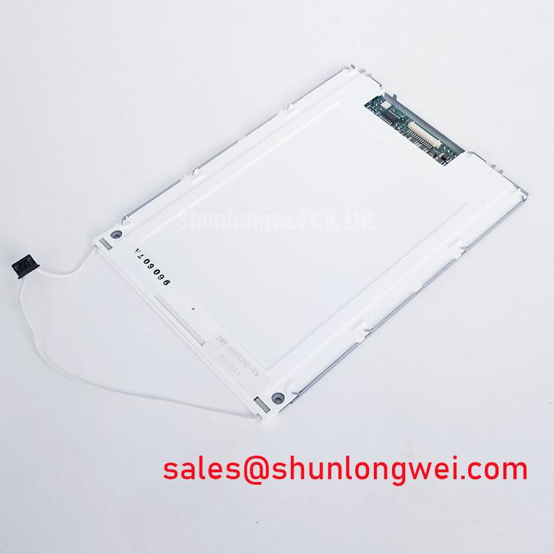
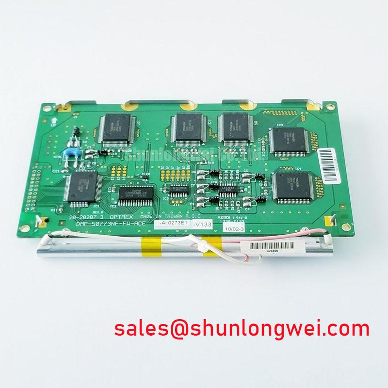
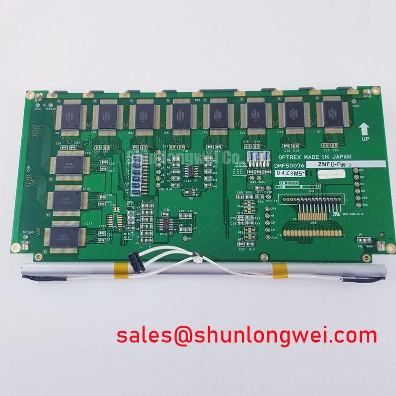
With power removed, inspect the DMF-50036ZNBU-FW display module perimeter, display surface, cable interface area, and mechanical retention points before reconnecting it to the host equipment. This is a Kyocera / OPTREX TFT-LCD Display Module identified as an Industrial Grade LCD/HMI Panel. Confirm the exact host-side interface, supply requirements, mechanical fit, and original timing documentation before a replacement panel is energized.
| Parameter | Available Identification |
|---|---|
| Model | DMF-50036ZNBU-FW |
| Manufacturer | Kyocera / OPTREX |
| Product Category | Industrial Grade LCD/HMI Panel |
| Module Type | TFT-LCD Display Module |
| Specification Status | Verify against the original manufacturer documentation and host equipment records |
For maintenance work, the part number alone does not establish electrical interchangeability. The service technician should compare the original panel documentation and the installed assembly for connector position, interface type, timing sequence, mounting arrangement, display resolution, optical characteristics, and backlight control requirements. These system-level details must be verified against the original equipment documentation rather than inferred from the model designation.
Viewing Cone Evaluation for Multi-Angle Consoles
Start visual assessment with the original display operating beside the replacement candidate whenever possible. Show a neutral gray image, a black field, and separate red, green, and blue screens. Observe each image from the operator’s expected viewing positions rather than only from straight ahead. A panel used in a console can appear acceptable on-axis while showing contrast shift, color variation, or dark-state lifting when viewed from the side.
The DMF-50036ZNBU-FW is officially identified as a TFT-LCD module. The supplied factory information does not confirm IPS, MVA, TN, a symmetric 85°/85°/85°/85° viewing specification, anti-glare treatment, or a defined contrast ratio under high ambient illumination. Those characteristics should therefore be treated as verification items, not as confirmed properties of this specific model.
Design Consideration: legacy TN displays can exhibit angle-dependent grayscale reversal, while IPS and MVA technologies are commonly evaluated for more balanced off-axis viewing. That general behavior does not identify the liquid-crystal mode of this module. For a multi-angle operator console, assess the panel while displaying low-gray patterns and fine text at the actual mounting angle. If the host system has a cover lens, protective window, or touch overlay, carry out the assessment with those parts installed because reflections and surface haze can materially change perceived readability.
High ambient illumination requires a separate practical check. Direct sunlight, task lighting, and reflected overhead lamps can expose surface reflections that are not evident on a bench. The original panel documentation should be used to verify any specified anti-glare surface treatment and optical performance. A technician can compare reflected light shape, dark-image washout, and text legibility between the removed panel and the intended replacement without assigning an unverified optical rating to the module.
Where a display is being evaluated for a surgical navigation or ultrasound diagnostic terminal, this application is only a compatibility example. The equipment designer or service authority must verify clinical-system requirements, image-quality requirements, enclosure performance, and applicable regulatory obligations. A TFT-LCD module is not, by itself, evidence of medical-system certification or suitability for a particular diagnostic task.
Radiated Emissions Assessment Through Backplate and Cable Shield Continuity
Before attributing horizontal bands, pixel shimmer, or intermittent image disturbance to the panel, inspect the complete signal path. Check that the display cable is fully seated, its lock mechanism is engaged where applicable, and the cable has not been pinched against a sharp chassis edge. Examine the rear metalwork and grounding contacts for oxidation, loose fasteners, or missing conductive contact points introduced during previous service work.
The supplied factory information for DMF-50036ZNBU-FW does not state CISPR Class A or Class B compliance, shielded FFC or LVDS requirements, grounding topology, ferrite requirements, or immunity performance near variable-frequency motor drives. Such requirements belong to the finished equipment and its validated cable assembly. The module should not be represented as independently compliant with an equipment-level radiated-emissions standard.
Design Consideration: a continuous chassis reference, appropriate cable shielding where defined by the host design, and controlled return paths can help reduce common-mode noise coupling into display signals. In equipment installed near switching motors or inverter wiring, compare the symptom with drive activity. Observe whether interference changes during motor acceleration, braking, or altered switching conditions. If available, compare the waveform and signal integrity at the known-good path using appropriate measurement equipment. This approach helps distinguish display-path sensitivity from broader cabinet grounding or cable-routing issues.
Backplate grounding should follow the original equipment drawing. A multi-point chassis contact arrangement can be part of a system-level EMC strategy, but it is not an official specification of this display module unless confirmed in the original assembly documentation. Avoid adding arbitrary bonding jumpers or ferrite parts without determining whether they alter the intended return path, mechanical clearance, or serviceability.
Cold environments require another controlled observation. Liquid-crystal response can slow as temperature falls, which can present as trailing, delayed transitions, or a temporarily sluggish interface. The official information provided does not establish an operating temperature range, response-time value, heater-strip provision, or low-temperature behavior for this model. When a cold-start issue is reported, allow the equipment to stabilize under its intended operating conditions and compare the display response with the original service baseline. The system integrator should verify any permitted heater control strategy from the equipment documentation.
For broader test planning involving industrial display grounding, mechanical integration, and environmental assessment, refer to Industrial Display & HMI Solutions. In motion-control equipment, communication and drive architecture can also influence where noise is observed; Sercos III real-time communication provides useful background on industrial motion communication systems, though it does not define the interface specification of this display module.
Preventing Frame Lag and Image Smearing During Cold Storage and Outdoor Service
When a panel has been kept in a cold storeroom or removed from outdoor equipment, first inspect for moisture on the surface, cable contacts, and surrounding chassis before applying power. Condensation can create misleading symptoms ranging from temporary optical haze to unstable electrical contact. Let the complete assembly reach conditions permitted by the host equipment procedure before deciding that a display fault is present.
Design Consideration: low temperatures can increase liquid-crystal viscosity, extending visible gray transitions and making cursor movement or scrolling text appear less immediate. This is a display-physics effect that should be assessed through observation under controlled conditions rather than diagnosed from one visual symptom. The host controller, video timing source, cable integrity, supply stability, and display itself can all contribute to a slow or smeared image presentation.
The factory information supplied for DMF-50036ZNBU-FW does not confirm operation from −30°C to +85°C, gray-to-gray response performance, perimeter seal construction, thermal-cycle qualification, transmitter clock tolerance, or required data hold time. Do not use these values as product ratings. If the installed equipment is expected to run in a wide temperature environment, the system integrator should verify the panel’s approved limits from the original Kyocera / OPTREX documentation and the host equipment qualification record.
During replacement work, cable handling matters as much as the panel itself. Flexible display interconnects should follow the existing routing path and should not be creased, twisted, or trapped beneath the frame. Reinstall any cable guides, adhesive retainers, strain-relief features, and protective insulation found in the original assembly. A cable that is electrically connected but mechanically unsupported can produce intermittent faults when the enclosure door moves, the machine vibrates, or the panel frame is compressed during reassembly.
⚠️ Field Alert: Disconnect system power and confirm stored energy has been discharged before releasing or reconnecting the display cable, because live insertion can stress signal contacts and complicate fault isolation.
Long-duration static screens deserve attention during HMI commissioning. Status dashboards, fixed menu bars, and idle alarm pages can leave temporary image retention on some LCD assemblies under certain operating conditions. This is not a confirmed characteristic of the DMF-50036ZNBU-FW; it is a Design Consideration for the host user interface. Where the equipment software allows it, validate screen-management behavior with representative operating pages and follow the end-equipment provider’s intended display-management policy.
If the panel is used in an assembly with a separate board connection requiring soldered mechanical support, service practices should preserve the original joint geometry and support arrangement. General information on through-hole technology can help explain why leaded connections require suitable mechanical support, but it does not prescribe a repair method or construction detail for this TFT-LCD module.
Flashlight Dark-Shadow Optical Diagnostic for Logic and Backlight Isolation
Use a controlled bench sequence before removing the panel from the equipment. First, confirm that the host starts normally and that the display cable remains fully latched. Next, command a full red image, then a full green image, then a full blue image through the equipment’s approved service mode or known-good video source. Finally, display a black screen and a text or grid pattern. This sequence reveals whether missing color, fixed lines, flicker, incomplete refresh, or uneven illumination follows a repeatable pattern.
For a dark screen with suspected image activity, shine a flashlight across the display surface at roughly a 45-degree angle in a dim work area. A faint image can indicate that image data may still be present while the illumination path requires further investigation. No visible image does not prove a single cause. Check the host video source, interface cable, connector retention, panel supply sequence, display control signals, and any separate illumination circuitry specified by the original equipment design.
The available official information does not identify the backlight technology, backlight input requirements, dimming method, PWM frequency, PWM duty relationship, or brightness-control polarity of the DMF-50036ZNBU-FW. Values such as 200 Hz to 1 kHz are commonly discussed during system-level PWM dimming evaluation, but they are not official ratings for this panel. The system integrator should verify the required dimming input and behavior from the original panel documentation before applying a control signal.
When text appears to shimmer or brightness appears uneven, compare the symptom under a static image, moving content, and different brightness settings only when those controls are supported by the host equipment. Audible noise, visible flicker, or brightness nonlinearity can originate in the host backlight driver, the control waveform, the cable path, or the display assembly. A known-good signal source and a known-good cable assembly are often more informative than replacing multiple parts at once.
Fine vertical or horizontal line defects should be documented with high-resolution photographs of solid-color screens before panel removal. Note whether the line remains fixed through all primary colors, changes with gentle chassis movement, or is present only after warm-up. Avoid applying pressure to the active display area in an attempt to clear a line; pressure testing can introduce additional mechanical stress and makes subsequent evidence less reliable. This disciplined isolation process supports a practical repair decision while keeping the assessment tied to observable behavior and the verified identity of the Kyocera / OPTREX DMF-50036ZNBU-FW TFT-LCD Display Module.