IGBT’s “Optimus Prime”: What is an IGBT Module? (2025 Q3)
In the world of power electronics, the Insulated Gate Bipolar Transistor (IGBT) is a superstar. It’s the workhorse behind everything from variable frequency drives (VFDs) and solar inverters to electric vehicles. But as power demands escalate, a single, discrete IGBT often isn’t enough. Engineers face the challenge of paralleling multiple components, a process fraught with complexities like current sharing, thermal balancing, and parasitic inductance. This is where the “Optimus Prime” of power electronics enters the scene: the IGBT Module.
Just as the fictional Transformer combines multiple vehicles into one formidable robot, an IGBT module integrates multiple semiconductor dies, diodes, and substrates into a single, robust, and highly optimized package. It’s not just an IGBT in a bigger box; it’s a pre-engineered power system building block designed to solve the very problems that plague discrete designs. Understanding the “what” and “why” behind IGBT modules is fundamental for any engineer or procurement manager working on high-power systems.
From a Single Switch to an Integrated Powerhouse
At its core, a discrete IGBT is a three-terminal semiconductor switch that combines the simple gate-drive characteristics of a MOSFET with the high-current and low-saturation-voltage capability of a bipolar transistor. It excels at efficiently switching high voltages and currents. An IGBT module, however, takes this concept to the next level.
An IGBT module is a self-contained power component that houses multiple IGBT chips, often alongside their accompanying freewheeling diodes (FWDs), all mounted on an insulated substrate. These internal components are arranged in specific circuit configurations, known as topologies, to perform a complete power conversion function. The most common topologies include:
- Half-Bridge (or Phase Leg): The fundamental building block for most inverters, containing two IGBTs and two FWDs in series.
- H-Bridge: Four IGBTs and FWDs, used for controlling motor direction or in single-phase inverters.
- Three-Phase Bridge: Six IGBTs and FWDs (a “six-pack”), essential for three-phase motor drives and grid-tied inverters.
- Chopper: A single IGBT and FWD, used for DC-DC conversion.
By integrating these components, the module transforms a collection of individual parts into a single, reliable, and thermally efficient unit, ready to be bolted onto a heatsink and connected to a control circuit.
Deconstructing the Module: A Look Inside
Peeling back the plastic or ceramic housing of an IGBT module reveals a marvel of electromechanical engineering. Each component is chosen and placed with precision to maximize performance and reliability. Here’s a breakdown of the key internal parts:
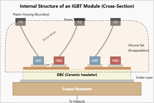
The Key Components:
- IGBT & FWD Dies: These are the bare semiconductor chips, the heart of the module. Manufacturers like Infineon, Mitsubishi, and Fuji Electric carefully select these dies for matched characteristics to ensure balanced performance when operating in parallel within the module. For example, a high-power module like the CM600DX-24T contains multiple chips to handle its rated 600A.
- Direct Bonded Copper (DBC) Substrate: This is a critical layer for both electrical connection and thermal dissipation. It consists of a ceramic insulator (typically Alumina or Aluminum Nitride) with copper layers bonded to both sides. The top copper layer is etched to create the circuit traces connecting the dies, while the bottom layer provides a path for heat to escape. You can learn more about its structure at Wikipedia.
- Baseplate: In most standard modules, the DBC substrate is soldered onto a thick copper baseplate. This baseplate serves two purposes: it provides a flat, stable surface for mounting to a heatsink and acts as a heat spreader, distributing the concentrated heat from the small dies over a larger area.
- Bond Wires: Heavy-gauge aluminum wires connect the terminals on the semiconductor dies to the copper traces on the DBC and to the main power terminals of the module. The geometry and length of these wires are carefully managed to minimize parasitic inductance.
- Housing, Gel, and Terminals: A rugged plastic housing protects the internal components. The inside is filled with a soft, dielectric silicone gel to prevent electrical arcing and protect the delicate bond wires from vibration and thermal expansion stress. The heavy-duty screw terminals provide secure connections for power buses and the smaller pins connect to the gate driver circuit.
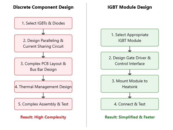
IGBT Module vs. Discrete IGBT: A Tale of Two Designs
For an engineer designing a power system, the choice between using multiple discrete IGBTs or a single IGBT module is a critical one. While discrete components might seem cheaper upfront, a system-level analysis often reveals a different story. The following table compares the two approaches across key engineering factors.
| Parameter | Discrete IGBTs | IGBT Module |
|---|---|---|
| Power Density | Lower. Requires significant PCB space for multiple components, gate drivers, and interconnects. | Higher. Integrates a full power stage into a compact, single package. |
| Thermal Management | Complex. Ensuring uniform temperature across multiple, separated components is a major challenge. Imbalances can lead to thermal runaway. | Simplified. A single, unified thermal interface to the heatsink. The baseplate ensures excellent heat spreading and a low Thermal Resistance. |
| Parasitic Inductance | High. Long PCB traces and bus bar connections create significant stray inductance, causing voltage overshoots and ringing during switching. | Very Low. Internal layout is highly optimized with short, wide conductors, minimizing inductance and improving switching performance. |
| Design & Assembly | Time-consuming. Requires careful layout, component matching, and complex assembly. Higher component count increases manufacturing complexity. | Fast and simple. A pre-tested, pre-optimized “plug-and-play” solution that drastically reduces design cycles and simplifies assembly. |
| Reliability | Lower. Multiple solder joints and mechanical connections increase potential failure points. Issues with current sharing can stress individual components. | Higher. Fewer external connections and a factory-controlled environment for die attachment and bonding result in a more robust system. |
As detailed in application notes like Infineon’s guide on paralleling IGBT modules, the benefits of the integrated approach become undeniable as power levels increase.
Application Case Study: 100kW Solar Inverter Design
To put this into perspective, let’s consider a real-world engineering challenge.
- Problem: A team is tasked with developing a new 100kW three-phase solar inverter. The initial prototype used discrete IGBTs in a TO-247 package. The design team struggled with several issues: the layout required a large, complex bus bar structure to connect the paralleled IGBTs, leading to significant voltage overshoot (~30% above DC link voltage) during high-speed switching. Furthermore, inconsistent thermal contact with the heatsink caused temperature mismatches of up to 25°C between devices, risking premature failure of the hotter components. The assembly process was manual, slow, and prone to error.
- Solution: For the second revision, the team switched to a single “six-pack” IGBT module. They selected a 1200V module that integrated all six IGBTs and six FWDs required for the three-phase bridge into one standard housing. The module was mounted directly to a single, optimized heatsink.
- Result: The impact was immediate and quantifiable. The low-profile, integrated power terminals and optimized internal layout of the module reduced the stray inductance dramatically, cutting voltage overshoot to less than 10%. This allowed the team to operate the system more efficiently and with greater reliability. The module’s single baseplate provided a uniform thermal path, reducing the temperature variance between dies to under 5°C. This greatly improved system lifespan and reduced the risk of common failure modes, which you can read more about in our guide to IGBT Failure Analysis. Overall, the design and assembly time for the power stage was reduced by an estimated 50%, significantly accelerating the project’s time to market.
Your Checklist for Selecting the Right IGBT Module
Choosing the correct IGBT module is more than just matching voltage and current. It requires a holistic view of the application’s demands. Here’s a practical checklist to guide your selection:
- Electrical Ratings (VCES, IC): Start with the basics. What is the maximum blocking voltage and continuous collector current your application requires? Always select a module with a safety margin (e.g., a 1200V module for an 800V DC bus).
- Topology: Does your application need a half-bridge, H-bridge, three-phase bridge, or another configuration? Choosing a module with the right internal circuit is the first step to simplifying your design.
- Thermal Performance (Rth(j-c)): The thermal resistance from junction-to-case is a critical parameter. A lower Rth(j-c) means the module can transfer heat more effectively to the heatsink, allowing it to run cooler or handle more power.
- Package Type and Footprint: Modules come in various industry-standard packages (e.g., EconoDUAL™, PrimePACK™, MiniSKiiP®). Consider the physical constraints of your design, terminal layout, and mounting requirements.
- Switching Frequency: Will your application operate at low frequencies (like a 50/60Hz motor drive) or high frequencies (like a welding power supply)? The IGBT technology generation (e.g., Fuji Electric’s X-Series vs. V-Series) determines the trade-off between switching losses and conduction losses.
- Special Features: Does the module include integrated temperature sensors (NTC thermistors)? Does it use enhanced technologies like Kelvin Emitter pins for cleaner gate signals or advanced substrate materials for higher thermal cycling capability?
For high-power industrial applications, a robust module is non-negotiable. For a comprehensive selection tailored to your needs, you can explore a wide variety of IGBT modules from leading manufacturers.
Conclusion: More Than the Sum of Its Parts
The IGBT module is a testament to the power of integration. It is not merely a convenience; it is a critical enabling technology for modern, high-power electronics. By consolidating multiple components into a single, thermally and electrically optimized package, modules solve inherent engineering challenges, reduce design complexity, and dramatically improve system reliability and power density.
From the discrete IGBT to the complex power module, the evolution reflects the relentless drive for more efficient and powerful systems. The next time you see a VFD, a wind turbine, or an EV fast charger, remember the “Optimus Prime” inside—the IGBT module, silently and efficiently managing the immense flow of power that makes it all possible.