Introduction to IGBT (Insulated Gate Bipolar Transistor)
Power electronic devices play a crucial role in the Power Conversion System (PCS), enabling the conversion and control of electrical energy. Among these devices, Insulated Gate Bipolar Transistor (IGBT) stands out as one of the most commonly used power devices. Today, let’s delve into the fundamentals of IGBT.
What is IGBT?
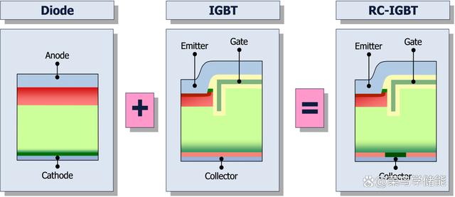
IGBT, or Insulated Gate Bipolar Transistor, combines the advantages of Giant Transistor (GTR) and Power Metal-Oxide-Semiconductor Field-Effect Transistor (Power MOSFET). It features a three-terminal structure: gate, collector, and emitter.
In simple terms, IGBT is a high-power electronic device functioning as a non-latching switch. It lacks voltage amplification capabilities, acting as a conductor during conduction and an open circuit during cutoff. Its key characteristics include high voltage, high current, and high-speed operation.
Composition of IGBT
IGBT typically consists of three terminals: collector, emitter, and gate. Both collector and emitter have metal layers, while the gate features a metal material with a silicon dioxide layer. Structurally, IGBT is a semiconductor device composed of four layers, integrating the arrangement of PNP and NPN transistors.
Internal Structure of IGBT Module
- Heat Sink: Located at the bottom, it efficiently dissipates the heat generated by IGBT switching.
- DBC Substrate (Direct Bonded Copper Substrate): Comprising three layers, the middle layer is a ceramic insulation layer, sandwiched between upper and lower copper layers. It serves as an insulating material with conductive patterns etched on the front side, directly connecting to the heat sink on the back, eliminating the need for etching.
- IGBT Chip: The core component of the module.
- Diode Chip: Flows current opposite to IGBT, used for anti-parallel connection.
- Bonding Wires: Commonly used to connect IGBT and diode chips to the copper layers on the DBC substrate. Aluminum and copper wires are the two commonly used bonding wire materials.
Working Principle of IGBT
The primary operating principle of IGBT involves controlling the flow of holes and electrons in the semiconductor layer by manipulating the gate voltage. This control governs the conduction and cutoff states of the device.
- When the gate voltage is positive, holes and electrons in the gate region move towards the base and emitter, forming a current path, allowing IGBT to conduct.
- When the gate voltage is negative, holes and electrons in the gate region move in the opposite direction, disrupting the current path, leading to IGBT cutoff.
Advantages and Disadvantages of IGBT
Advantages:
- Strong handling of voltage and current.
- Extremely high input impedance.
- Low voltage can switch very high currents.
- Negligible input current and low input losses.
- Low on-state resistance.
- Low gate drive requirements.
- Easily switched on by applying a positive voltage and switched off by applying zero or slightly negative voltage.
- High current density for smaller chip size.
- Higher power gain compared to BJT and MOSFET.
- Bipolar nature enhances conductivity for increased safety.
Disadvantages:
- Switching speed is lower than MOSFET.
- Unable to handle AC waveforms without additional circuitry.
- Limited ability to block higher reverse voltages.
- Higher cost compared to BJT and MOSFET.
- Similar P-N-P-N structure to thyristor leads to latch-up issues.
Applications of IGBT in Energy Storage
The robust growth of energy storage, driven by policies such as the 30-60 Carbon Peak and Carbon Neutrality, has propelled the development of IGBT. In the realm of photovoltaics and wind power, IGBT serves as a vital component in power switches. Inverters, crucial for energy conversion in both DC-DC converters and photovoltaic inverters, rely on IGBT as a power switch. The efficiency of inverters is significantly influenced by power losses, comprising conduction and switching losses.
IGBT is well-suited for applications with lower switching frequencies and high currents. Its lower conduction losses compared to MOSFET make it preferable for higher current applications. MOSFETs excel in high-frequency, low-current applications. In the context of inverters, especially in modules for high-power three-phase inverters, IGBT modules are commonly used.