
Content last revised on September 19, 2026
Transient Dynamics & Electrical Design: Evaluating Post Surge Reverse Voltage Block on 2DI100A-1K
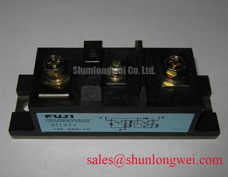
With power isolated and the DC bus fully discharged, begin service work by checking terminal tightness, heat spreader contact, and cold resistance paths against the removed module and the equipment schematic. The 2DI100A-1K from Fuji Electric is identified as a two-diode power diode module with a stated 100A current rating and 1000V voltage rating. Confirm the terminal designations, mechanical footprint, and electrical role in the original assembly before any replacement decision.
| Official identification | Published value |
|---|---|
| Manufacturer | Fuji Electric |
| Part number | 2DI100A-1K |
| Product category | Two-diode power diode module |
| Rated current | 100A |
| Voltage rating | 1000V |
After a suspected surge event, do not reconnect the diode module simply because a meter shows an open circuit in one direction. Isolate connected capacitors, snubbers, transformers, and parallel paths first, then compare each accessible diode path with the circuit documentation and a known serviceable assembly where available. A diode module must be assessed as part of its rectifier network, because external surge suppression components, fuse operation, contaminated terminals, or damaged copper tracks can all alter a basic bench reading.
The available product identification indicates a 100A power diode module with a 1000V voltage rating, but does not provide a published sinusoidal half cycle surge current value, reverse voltage number beyond the stated rating, fuse coordination value, or terminal torque value. Those figures must be taken from the original Fuji Electric documentation for the exact installed revision before they are used in a protection calculation or acceptance test. In particular, an I²t comparison is only meaningful when the fuse clearing characteristic, prospective fault current, ambient condition, and module datasheet limit are all known.
For medium frequency induction melting or hardening furnace equipment, maintenance personnel can inspect whether the diode module is located in an auxiliary supply, sensing supply, excitation circuit, or another rectified branch before judging operational stress. The main power topology may include related rectifier devices such as the 2DI100Z-140, but electrical interchangeability cannot be assumed from a similar product family name. Confirm the required blocking boundary, terminal layout, and heat sinking arrangement from the machine documentation.
Assembly Integrity & Layout Architecture: Implementing AC to DC Transfer Characteristics across V for 2DI100A-1K
A diode module has no firing angle control. Terms such as firing angle from zero to 150 degrees, reactive power demand from phase control, and gate pulse sequencing apply to controlled rectifier devices rather than to this diode module. The 2DI100A-1K conducts according to the instantaneous polarity applied to its diode elements and the load conditions imposed by the surrounding circuit. If controlled rectification is observed in the equipment, identify the actual controlled semiconductor separately instead of assigning that function to this module.
During a repair, trace the module terminals and the positive and negative DC paths on the schematic. Verify cable routing, terminal insulation, busbar contact surfaces, and the polarity of any downstream electrolytic capacitors. A distorted DC waveform can arise from upstream supply abnormalities, load behavior, open circuit connections, or failure in a separate control stage. It should not be assigned to the diode module without measurement at its relevant terminals under safe, documented test conditions.
Field Alert: Disconnect and discharge the equipment before moving any module connection, and tighten mounting and power hardware only to the original equipment or manufacturer specified torque.
Design Consideration: keep the AC and DC current paths mechanically secure and as direct as the established equipment layout allows, especially where current transitions can induce unwanted voltage disturbance. The system engineer should verify voltage waveforms and peak margins at the installed terminals during controlled commissioning. Fuji Electric’s global power semiconductor information is an appropriate manufacturer reference point when matching original product documentation to the wider equipment record.
2DI100A-1K Thermal Electrical Optimization: Preventing Localized Gate Hotspot Burnout Practical Tuning
There is no published gate connection, gate trigger specification, holding current, or gate pulse rise time for the 2DI100A-1K within the supplied product information. Gate hotspot analysis, back porch holding current, and multipulse firing methods therefore must not be applied to this diode module. Treating a diode module as a gate-controlled device can lead technicians to probe the wrong terminals or overlook the real source of a control fault.
Thermal assessment remains relevant, but it must stay within verified information. Inspect the mounting face for debris, uneven contact evidence, corrosion, or signs that the module has moved relative to its heat sink. Examine the surrounding thermal interface material for continuity and follow the machine builder’s specified service method. If temperature rise is suspected, measure the broader assembly under approved load conditions and compare readings with the equipment’s known operating baseline. No junction temperature limit or thermal resistance value is stated in the supplied data, so neither should be estimated as a product-specific limit.
When evaluating a possible service substitute, the 2DI100D-050C can be reviewed as a related inventory reference. The repair decision still requires confirmation of its voltage rating, current capability, terminal pattern, package dimensions, thermal interface, and circuit function against the original module. This is a compatibility review, not a prescriptive replacement recommendation.
Assembly Integrity & Layout Architecture: Implementing RC Snubber Network Optimization to Prevent for 2DI100A-1K
An RC snubber, MOV, series reactor, or other suppression network belongs to the system-level design, not to the stated factory identity of this module. The supplied information does not define a snubber capacitance, resistance, allowable dv/dt, allowable di/dt, or reactor characteristic for the 2DI100A-1K. Do not install numerical values copied from an unrelated rectifier assembly.
Design Consideration: assess suppression components only after establishing the actual source of switching disturbance, the measured waveform at the module terminals, the connected load, and the available reverse-voltage margin. A snubber can reduce repetitive disturbance in a suitable circuit, while an incorrectly selected network can increase dissipation or alter the existing transfer behavior. The system engineer should validate any component selection with controlled measurements on the completed equipment.
For technicians assessing difficult induction heating power supply faults, inspect the condition and connections of existing RC networks and MOV parts, then compare the installation to the service schematic before changing components. Broader maintenance and test context can be found in Future of Power Electronics. The practical repair objective is to restore the documented circuit arrangement while retaining verified electrical and mechanical boundaries for the installed diode module.