

Content last revised on September 15, 2026
Benchtop Waveform Tuning: Mitigating Stress via High-Current DC Rectifier Topologies for 2DI100D-050C
Verify the marked terminals against the original circuit drawing, then perform a cold-state diode test with the module fully isolated from the DC link.
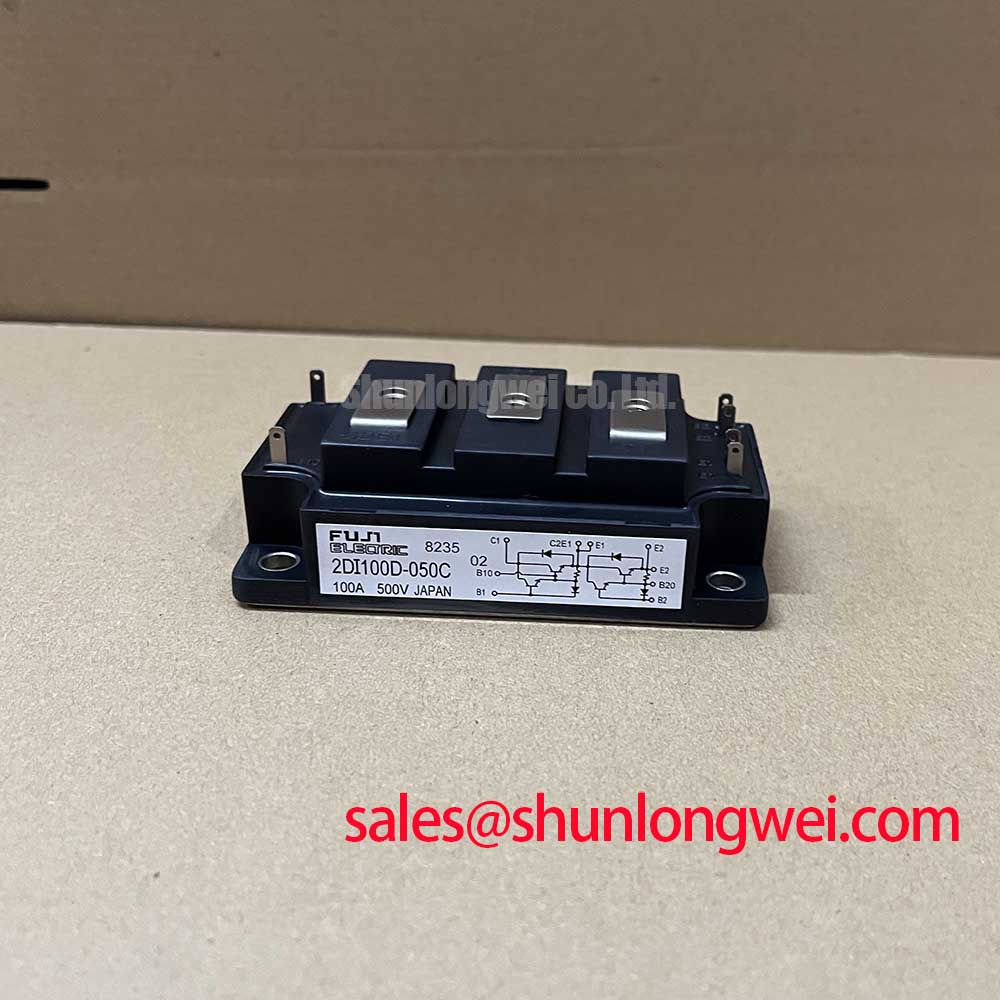
The Fuji Electric 2DI100D-050C is specified with a 500 V collector-emitter voltage rating and a 100 A collector current rating at TC = 25°C. These are official specification values and should be compared with the rectifier operating envelope before any replacement decision is made. A high-current green hydrogen electrolyzer DC power rectifier may use six-pulse or twelve-pulse bridge arrangements, but the suitability of this device depends on the complete bridge topology, transformer arrangement, commutation behavior, and cooling system.
For incoming inspection, confirm the terminal markings and compare diode-test readings with a known-good reference from the same approved configuration. A forward reading in one polarity and blocking behavior in the reverse polarity can help identify gross junction abnormalities, but a handheld meter cannot reproduce the module’s rated current, switching stress, or thermal conditions. Any unexpected reading should be checked against the original circuit and measured again after confirming that parallel paths, snubbers, and transformer windings are not influencing the result.
In a twelve-pulse rectifier, an interphase transformer may be used to manage current sharing between bridge sections. This current-sharing function is determined by the complete magnetic and control design, not by the module rating alone. Designers should verify the current waveform at the bridge terminals and inspect commutation overlap, voltage overshoot, and thermal balance during controlled testing. The supplied product information does not define a fuse I²t coordination table, terminal torque value, or complete terminal connection diagram, so those details must be taken from the applicable Fuji Electric documentation and the equipment service drawing.
Transient Dynamics & Electrical Design: Type-2 Coordination and Sub-Cycle Fault Protection
The published short-circuit withstand time is 10 µs, identified here as an official specification. This value should not be treated as a guaranteed fuse-clearing interval or as permission to expose the module repeatedly to a dead-short event. Semiconductor fuse selection requires the fuse manufacturer’s clearing I²t data, the available fault current, circuit inductance, DC-link conditions, and the withstand characteristics of every semiconductor in the current path.
A Type-2 coordination study should compare the fuse clearing energy with the documented short-circuit and surge limits of the complete assembly. The result must be validated through the equipment protection study and controlled testing; the available product data does not support a claim of zero mechanical or electrical damage under every fault condition. Designers should also examine busbar layout and minimize parasitic loop inductance to reduce turn-off overshoot, then verify peak voltage against the module’s 500 V VCES rating.
Gate-drive requirements must not be inferred from the model number. If this device is installed in a converter leg that includes separately controlled switching elements, the driver should be checked for dead-time protection, desaturation response, soft shutdown behavior, and isolation performance. Gate-loop damping and common-mode transient suppression remain system-level design considerations. The supplied parameters do not specify gate voltage, gate charge, VCE(sat), CMTI, or SCSOA behavior for this product.
Transient Dynamics & Electrical Design: Power Factor Degradation and Harmonic Mitigation
A six-pulse bridge naturally produces characteristic input-current harmonics, while a twelve-pulse arrangement can reduce selected harmonic components when the phase-shifting transformer and interphase network are correctly designed. Firing-angle control, where applicable to the associated controlled rectifier, changes the AC-to-DC operating point and reactive power demand. Those transfer characteristics cannot be assigned to the 2DI100D-050C alone because the model data supplied here does not specify thyristor trigger parameters such as IGT or VGT.
For an electrolyzer rectifier evaluation, measure line current, DC output ripple, displacement power factor, and distortion at the intended operating points. Compare the waveforms with the transformer nameplate data and the control system’s firing strategy. A pulse train or strong triggering method may be appropriate for a thyristor gate circuit, but it must not be applied to this diode module without a verified circuit diagram. Where switching devices and optical or digital isolators are present elsewhere in the power stage, the system integrator should verify isolation timing and CMTI capability against measured common-mode transients.
For a neutral comparison during procurement, engineers may also review the electrical data of 2DI200A-050. That device should not be treated as a drop-in substitute without checking voltage, current, package geometry, terminal arrangement, thermal resistance, and the original equipment approval requirements.
2DI100D-050C Operational Boundaries: Uniform Heatsink Contact Pressure
The official thermal resistance values supplied for this model are 0.24 °C/W from junction to case for the IGBT and 0.40 °C/W from junction to case for the FWD. These values describe the thermal path under the manufacturer’s specified test conditions. Actual junction temperature depends on power loss, mounting quality, heatsink temperature, interface material, airflow, and the duty cycle of the complete rectifier.
Before installation, clean the mating surfaces, inspect the base and heatsink for visible damage, and apply the interface material using the equipment manufacturer’s approved process. Uniform contact pressure is important because local gaps can increase thermal impedance and create uneven temperature distribution. The correct mounting sequence and torque must come from the Fuji Electric mechanical drawing or the original equipment documentation; no model-specific torque value was supplied here.
The relationship between different material expansion rates can contribute to mechanical stress during thermal cycling. For general background on coefficient of thermal expansion mismatch in semiconductor assemblies, consult Thermal Expansion Coefficient. This is a materials engineering consideration, not a field-life prediction for this module. Engineers evaluating renewable-energy or heavy industrial converters can also refer to the Industrial Applications guide for broader system context.
💡 Bench Tip: Use ESD precautions, record the cold-state reference readings before energizing the test fixture, and never connect or remove power terminals while the DC link is charged.
| Parameter | Specified value | Status |
|---|---|---|
| Collector-emitter voltage, VCES | 500 V | Official Specification |
| Collector current, IC at TC = 25°C | 100 A | Official Specification |
| Short-circuit withstand time, tsc | 10 µs | Official Specification |
| Junction-to-case thermal resistance, IGBT | 0.24 °C/W | Official Specification |
| Junction-to-case thermal resistance, FWD | 0.40 °C/W | Official Specification |