Intelligent Power Module (IPM): How Convenient is an IGBT with Integrated Drive and Protection? (2025 Q3)
The Engineer’s Dilemma: The Hidden Complexities of Discrete IGBT Design
In the world of power electronics, designing a robust and efficient inverter or motor drive from discrete components is a significant engineering challenge. While a standard IGBT module is a powerful switch, it’s just one piece of a complex puzzle. Engineers must meticulously design, test, and validate the surrounding circuitry, which includes gate drivers, level shifting, and a suite of protection features. This process is not only time-consuming but also fraught with potential pitfalls.
Consider the typical design cycle for a three-phase motor drive:
- Gate Drive Design: Crafting a stable and powerful Gate Drive circuit that can provide the necessary current to quickly charge and discharge the IGBT’s gate capacitance, ensuring efficient switching while avoiding spurious turn-on. This involves selecting driver ICs, bootstrap components for high-side switches, and ensuring proper isolation.
- Protection Circuitry: Implementing reliable protection is non-negotiable. This means designing separate circuits for over-current detection (often using sense resistors or desaturation detection), short-circuit protection, under-voltage lockout (UVLO) for the driver supply, and over-temperature sensing.
- PCB Layout: The physical layout is critical. Poorly placed components or long trace lengths can introduce parasitic inductance, leading to voltage overshoots, EMI/EMC issues, and even catastrophic device failure. The gate drive loop must be as tight as possible.
- Component Matching: Ensuring that the performance characteristics of the IGBTs and their associated driver components are well-matched for balanced performance, especially in paralleled applications.
Each of these steps adds layers of complexity, increases component count, enlarges the PCB footprint, and extends the time-to-market. This is the very pain point that the Intelligent Power Module (IPM) was designed to solve.
What Exactly is an Intelligent Power Module (IPM)?
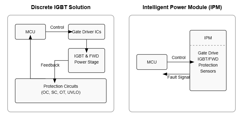
An Intelligent Power Module, or IPM, is a highly integrated power semiconductor device that combines power switches (typically IGBTs with Freewheeling Diodes – FWDs) with dedicated, optimized drive and protection circuits in a single, compact package. It is essentially a “plug-and-play” power stage, transforming a complex design challenge into a single, reliable component.
Beyond the IGBT: A Look Inside the IPM
An IPM is far more than just IGBTs in a box. A typical modern IPM, such as a Mitsubishi Electric DIPIPM™, contains a carefully engineered ecosystem of components:
- Power Stage: This consists of the IGBTs and FWDs, often arranged in a specific topology like a 6-pack (for a three-phase bridge), half-bridge, or chopper configuration. These silicon chips are selected and matched by the manufacturer for optimal performance.
- Gate Driver ICs: Custom-designed driver ICs are co-packaged with the IGBTs. These drivers are perfectly matched to the IGBTs’ gate characteristics, providing optimized switching speed, controlled di/dt and dv/dt, and minimizing switching losses.
- Level-Shifting Circuitry: For bridge topologies, integrated high-voltage level-shifters allow ground-referenced logic signals from a microcontroller to safely control the high-side IGBTs, whose emitters are floating at high potentials.
- Bootstrap Circuitry: Most IPMs include integrated bootstrap diodes and, in some cases, current-limiting resistors, simplifying the power supply design for the high-side gate drivers.
The “Intelligent” Core: Integrated Gate Drivers and Protection
The “intelligence” of an IPM lies in its built-in feedback and protection functions. These are not just add-ons; they are integrated at the die level, offering response times and reliability that are difficult to achieve with discrete external circuits.
Key integrated protections typically include:
- Short-Circuit Protection (SC): The module can detect a short-circuit condition and safely shut down the IGBTs within microseconds, preventing catastrophic failure. This is a critical feature that defines the device’s Short-Circuit Withstand Time .
- Over-Current Protection (OC): Protects against sustained overloads that may not be a hard short-circuit.
- Over-Temperature Protection (OT): An integrated temperature sensor (often an NTC thermistor or a die-level sensor) provides a signal to the control logic or can trigger an automatic shutdown if the module exceeds its safe operating temperature.
- Under-Voltage Lockout (UVLO): This ensures that the gate driver supply voltage is sufficient for proper operation. If the voltage drops too low, the IGBTs are turned off to prevent them from operating in the linear region, which would cause high conduction losses and likely lead to failure.
- Fault Feedback: When a protection feature is triggered, the IPM sends a single, unified “Fault” signal back to the master controller (MCU). This simplifies the error handling logic in the system’s firmware.
IPM vs. Discrete IGBTs: A Head-to-Head Engineering Comparison
For an engineer or purchasing manager, the decision between an IPM and a discrete solution comes down to a trade-off between various factors. Here’s a direct comparison:
| Metric | Intelligent Power Module (IPM) | Discrete IGBT + Driver Solution |
|---|---|---|
| Design Complexity & Time-to-Market | Significantly lower. The most complex parts of the power stage are pre-engineered, tested, and validated. Dramatically accelerates the design cycle. | High. Requires expert-level knowledge in gate driving, protection circuit design, and PCB layout for power electronics. Longer development and testing phases. |
| Reliability & Performance | Higher system reliability. Optimized gate drive and tight integration minimize parasitic inductances. Protection features are faster and more robust. | Highly dependent on design quality. Prone to issues from layout parasitics, component tolerances, and EMI. Performance can be excellent but requires more engineering effort to achieve. |
| PCB Footprint & Component Count | Very compact. A single module like the 6MBP25VAA120-50 replaces dozens of discrete components, leading to a much smaller and simpler PCB. | Large. Requires significant board space for IGBTs, drivers, optocouplers, protection components, and associated passives. |
| Total System Cost | Higher initial component cost, but lower total system cost due to reduced R&D, smaller PCB, simplified assembly, and improved reliability reducing warranty costs. | Lower Bill of Materials (BOM) cost for the components themselves. However, this is offset by higher development, testing, and assembly costs. May be more cost-effective for extremely high-volume products where NRE is amortized. |
| Design Flexibility | Less flexible. The engineer is locked into the specific performance characteristics (e.g., switching speed, protection thresholds) defined by the IPM manufacturer. | Maximum flexibility. Engineers can fine-tune every aspect of the gate drive and protection to meet very specific or unusual application requirements. |
Application Case Study: Simplifying a 5kW Variable Frequency Drive (VFD) Design
The Problem: A Complex and Bulky Discrete Design
An engineering team was tasked with developing a new 5kW VFD for industrial conveyor systems. Their initial approach used discrete components. The BOM included 6 individual 650V/50A IGBTs, 6 fast-recovery diodes, 3 high/low side gate driver ICs, multiple optocouplers for isolation, a complex desaturation detection circuit for short-circuit protection, a separate temperature sensor, and dozens of supporting resistors and capacitors. The resulting PCB was large, layout was challenging, and initial prototypes suffered from noise issues in the gate drive circuit.
The Solution: Switching to an IPM
Faced with a tight deadline, the team re-evaluated their strategy and switched to an IPM (Intelligent Power Module). They selected a module like the Fuji Electric 7MBR50VP120-50, which integrated the entire three-phase IGBT/FWD bridge, optimized gate drivers, and all necessary protection features into a single package. The design process was immediately simplified: the complex gate drive and protection layout was replaced by simple logic-level control signals from the MCU to the IPM and a single fault line from the IPM back to the MCU.
The Result: Quantifiable Gains in Performance and Reliability
The switch to an IPM yielded dramatic improvements:
- Component Count Reduction: The power stage component count dropped from over 50 components to just 1 IPM and a few external bootstrap capacitors.
- PCB Area Savings: The PCB footprint required for the power stage was reduced by approximately 55%.
- Development Time: The design, layout, and testing phase was shortened by an estimated 4 weeks, a 50% reduction.
- Enhanced Reliability: The integrated, factory-tested protection circuits provided more reliable and faster fault detection than the discrete implementation. EMI performance also improved due to the minimized parasitic inductance within the module.
Practical Selection Guide: How to Choose the Right IPM for Your Application
Choosing an IPM is more straightforward than a full discrete design, but it still requires careful consideration. Use this checklist as a guide:
- Check Basic Ratings: Ensure the IPM’s maximum voltage and current ratings (VCES, IC) exceed your application’s requirements with a sufficient safety margin (typically 20-30%).
- Confirm the Topology: Does the IPM match your circuit? Common topologies are 6-packs for three-phase inverters, 7-packs (including a brake chopper), and half-bridges.
- Evaluate Switching Characteristics: Look at the switching loss (Eon, Eoff) and conduction loss (VCE(sat)) data in the datasheet. Ensure these are acceptable for your target switching frequency and load profile to manage thermal performance.
- Review the Protection Suite: Does the IPM include all the protections you need? Verify the thresholds for over-current and the trip time for short-circuit protection.
- Consider the Package and Thermal Interface: The module’s package and its thermal resistance (Rth(j-c)) will determine your heatsinking requirements. Ensure you can adequately cool the device in your intended enclosure.
- Check Control Interface Compatibility: Verify that the IPM’s logic input levels (VIH, VIL) are compatible with your microcontroller’s GPIO voltage (e.g., 3.3V or 5V).
- Assess Manufacturer Support: Choose a reputable manufacturer that provides comprehensive datasheets, application notes, and good technical support.
Key Takeaways: Is an IPM Always the Right Choice?
Intelligent Power Modules represent a massive leap in convenience, reliability, and speed for power electronics design. By integrating the most challenging aspects of a power stage into a single, optimized component, they allow engineering teams to focus on system-level features and software, rather than wrestling with the intricacies of gate drives and protection circuits.
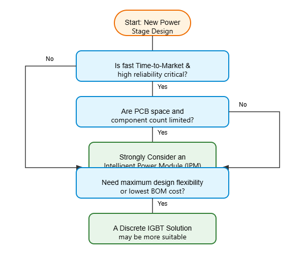
For applications where time-to-market, space constraints, and high reliability are paramount—such as industrial motor drives, servo amplifiers, home appliance inverters, and small renewable energy systems—the IPM is often the superior choice. While a discrete solution may offer a lower initial BOM cost and greater design flexibility, this often comes at the expense of higher development costs and increased system complexity.
Ultimately, the IPM empowers engineers to build more robust and compact power systems, faster. If your goal is to de-risk your project and accelerate your development schedule, exploring the wide range of available IPM modules is a crucial step in your design journey.