IGBT Module Selection Core Trio: Voltage Margin, Current Density, and Thermal Management in Practice
In the world of power electronics—from industrial VFDs and servo drives to renewable energy inverters—the IGBT module is the heart of the system. Its performance directly dictates efficiency, reliability, and cost. However, selecting the right module is far more complex than simply matching the voltage and current ratings on a datasheet’s front page. Engineers often face a critical challenge: translating catalog specifications into real-world performance. This article provides a battle-tested framework for engineers and technical decision-makers, focusing on the three pillars of robust IGBT selection: voltage margin, current density, and thermal management.
We will move beyond theoretical numbers to explore how system-level factors like DC bus voltage fluctuations, switching frequencies, and heatsink design ultimately determine if a chosen module will succeed or fail in the field.
Foundational Pillar 1: Engineering the Right Voltage Margin (Vces)
The collector-emitter breakdown voltage (Vces) is the absolute maximum voltage the IGBT can block. Exceeding this rating, even for a few nanoseconds, can lead to catastrophic failure. While selecting a module with a Vces rating higher than the nominal DC bus voltage seems straightforward, the real engineering challenge lies in accounting for transient overvoltages.
In practice, the DC bus is not a perfectly stable voltage source. Overvoltage spikes are inevitably generated during switching, primarily due to the rapid change in current (di/dt) flowing through the circuit’s stray inductance (Ls). This relationship is defined by the formula: V = Ls * (di/dt). Even small amounts of inductance in busbars, PCBs, and module terminals can generate significant voltage spikes at the high switching speeds of modern inverters.
A common rule of thumb is to select an IGBT with a voltage rating that is at least 1.5 to 2.0 times the nominal DC bus voltage. For a system with a 600V DC bus, a 1200V IGBT module like the classic BSM50GD120DN2 is the standard choice. This provides a sufficient safety margin to absorb overvoltage spikes caused by stray inductance and potential line voltage surges.
Case Study: The Hidden Danger of Stray Inductance
Consider a 50kW motor drive operating on a 580V DC bus. An engineer might be tempted to use a 1000V rated IGBT to save costs. However, during rapid deceleration (regenerative braking), the motor acts as a generator, causing the DC bus voltage to rise. Simultaneously, fast turn-off switching creates a high di/dt. If the busbar layout is not optimized and has a stray inductance of just 50 nH, with a turn-off di/dt of 2000 A/µs, the induced voltage spike would be:
V_spike = 50 nH * (2000 A / 1 µs) = 100V
This 100V spike, added to a bus voltage that might have already swelled to 650V during regeneration, brings the total voltage across the IGBT to 750V. While still under the 1000V rating, this leaves little room for further transients from the grid. A more conservative design using a 1200V module provides the necessary headroom for a reliable, long-term solution. For a deeper understanding of device structure, see our guide on deconstructing the IGBT’s hybrid structure.
Key Takeaways: Voltage selection is not about the nominal DC voltage; it’s about the peak voltage the device will experience. Always factor in stray inductance and potential line surges, and apply a conservative derating factor (typically 60-70% of Vces) for robust design.
Foundational Pillar 2: Decoding Current Density – Rated Current (Ic) vs. Real-World Capability
The rated continuous collector current (Ic) listed prominently on datasheets is one of the most misunderstood parameters. This value is typically specified at an ideal, and often unrealistic, case temperature (Tc) of 25°C. In any real-world application, the case temperature will be significantly higher, meaning the module’s actual continuous current capability is much lower than the “headline” number.
The true current-carrying capacity is limited by the maximum allowable junction temperature (Tj,max), which is typically 150°C or 175°C. Therefore, an engineer must work backward from the thermal limitations, not forward from the Ic rating. The choice often involves a trade-off between conduction losses (Vce(sat)) and switching losses (Eon, Eoff), which are influenced by the IGBT’s chip technology and current density.
Application Context is King: VFD vs. Solar Inverter
The optimal current rating depends heavily on the application’s load profile and switching frequency.
- Variable Frequency Drives (VFDs): In motor control, especially at lower speeds, the switching frequency is relatively low (e.g., 2-8 kHz). Here, conduction losses, determined by the collector-emitter saturation voltage (Vce(sat)), are dominant. A module with a lower Vce(sat), even if it has slightly higher switching losses, would be more efficient.
- Solar Inverters or UPS: These applications often run at higher switching frequencies (e.g., 16-30 kHz) to reduce the size of magnetic components. In this scenario, switching losses (Eon and Eoff) become the primary source of heat. A module optimized for lower switching energy is preferable, even if its Vce(sat) is slightly higher.
The table below illustrates this trade-off using two hypothetical 1200V, 100A modules.
| Parameter | Module A (Optimized for Low Vce(sat)) | Module B (Optimized for High Speed) | Engineering Implication |
|---|---|---|---|
| Vce(sat) @ 100A, 150°C | 1.8V | 2.2V | Module A has lower heat generation during the ‘on’ state. |
| Total Switching Energy (Ets) @ 100A, 150°C | 8 mJ | 5 mJ | Module B generates less heat during turn-on and turn-off. |
| Ideal Application | Low-frequency motor drives (VFD) | High-frequency solar inverters, UPS | Matching the module’s strength to the application’s loss profile is critical. |
Key Takeaways: Ignore the datasheet’s Ic rating at Tc=25°C. Analyze the application’s switching frequency to determine whether conduction or switching losses will dominate. Select a module whose characteristics (low Vce(sat) or low Ets) best match that loss profile to minimize total heat generation.
Foundational Pillar 3: Thermal Management – The Ultimate Arbiter of Performance
Ultimately, an IGBT module’s performance is dictated by how effectively you can remove the heat it generates. This is the realm of thermal management, governed by the concept of thermal resistance (Rth). The total thermal resistance from the silicon chip (junction) to the ambient air (Rth(j-a)) is a sum of several components:
Rth(j-a) = Rth(j-c) + Rth(c-h) + Rth(h-a)
- Rth(j-c) (Junction-to-Case): An intrinsic property of the module, found in the datasheet. This represents how efficiently heat travels from the chip to the module’s baseplate.
- Rth(c-h) (Case-to-Heatsink): This is determined by the Thermal Interface Material (TIM) used between the module and the heatsink. The quality, thickness, and application of the TIM are critical.
- Rth(h-a) (Heatsink-to-Ambient): This depends entirely on the heatsink design and airflow (natural or forced convection).
The goal is to ensure the junction temperature (Tj) never exceeds its maximum limit under worst-case operating conditions. The junction temperature can be estimated as:
Tj = Ta + (P_total * Rth(j-a))
Where Ta is the ambient temperature and P_total is the total power loss (conduction + switching). For high-power applications requiring hundreds of amps, such as wind power converters, a module like the 2MBI900VXA-120P-50 features a large baseplate and low intrinsic Rth(j-c) specifically to facilitate effective heat removal.
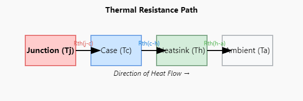
Figure 1: Thermal Resistance Path from IGBT Junction to Ambient Air
Practical Thermal Engineering Checklist
Effective thermal design is a systematic process. Use this checklist to avoid common pitfalls:
- Heatsink Selection: Is the heatsink’s Rth(h-a) rating low enough to dissipate the calculated total power loss while maintaining a safe Tj?
- TIM Application: Is the correct type of TIM being used? Is it applied evenly and at the manufacturer’s recommended thickness to minimize Rth(c-h)?
- Mounting Torque: Are the module’s mounting screws tightened to the specified torque? Uneven or incorrect torque can warp the baseplate, creating gaps and increasing thermal resistance.
- Airflow Analysis: Is there sufficient, unobstructed airflow across the heatsink fins? Consider the impact of dust, aging fans, and nearby heat sources.
Ignoring these practical details can lead to thermal runaway and premature failure, a topic explored further in our guide to IGBT failure analysis.
Key Takeaways: Thermal management is the ultimate enabler of current capability. A robust thermal design, from TIM selection to airflow verification, is just as critical as the electrical design for ensuring system reliability.
Synthesizing the Trio: A Practical Selection Workflow
Combining these three pillars, we can establish a logical workflow for selecting an IGBT module for a new design, such as a 50kW servo drive.
- Establish Voltage Margin:
- Application Requirement: 580V nominal DC bus.
- Decision: Select a 1200V class module to provide a ~2x safety margin against transients.
- Estimate Current and Initial Ic Selection:
- Application Requirement: 50kW output, leading to an estimated RMS current of ~85A and a peak repetitive current of ~150A.
- Decision: Start by evaluating 1200V modules in the 150A to 200A Ic range. A module like the PM100RLA060 (though a 600V IPM) exemplifies how integrated solutions can simplify this process for smaller drives, but for our 1200V case, we’d look for a discrete module.
- Perform Thermal Calculation:
- Analysis: At a switching frequency of 8 kHz, calculate the total power loss (P_total) using Vce(sat) and Ets values from the candidate module’s datasheet at the expected operating current.
- Verification: Using a realistic heatsink (e.g., Rth(h-a) = 0.1 °C/W) and TIM (e.g., Rth(c-h) = 0.05 °C/W), calculate the expected junction temperature. Assume a worst-case ambient temperature of 50°C.
- Example: If P_total is 350W and the module’s Rth(j-c) is 0.08 °C/W, then Tj = 50°C + (350W * (0.08 + 0.05 + 0.1) °C/W) = 50 + 80.5 = 130.5°C.
- Iterate and Finalize:
- Result: The calculated Tj of 130.5°C is safely below the typical 150°C/175°C limit, providing a good reliability margin. The selected module is suitable.
- Contingency: If Tj were too high, the options would be to select a module with lower total losses, a larger module with a lower Rth(j-c), or to improve the cooling system (better heatsink or fan). An example of a very high voltage module for extreme applications is the CM600HG-130H, designed for the most demanding thermal environments.
Conclusion: From Component Selection to System Reliability
Selecting the right IGBT module is an exercise in holistic system design, not just datasheet matching. By systematically analyzing voltage margin, understanding the true meaning of current capability, and engineering a robust thermal solution, designers can build a foundation for a reliable and efficient power conversion system. The three core pillars—voltage, current, and heat—are inextricably linked. A decision made in one area directly impacts the others. Mastering this interplay is the key to moving from a design that works on paper to one that performs reliably for years in the field. For expert guidance on your next project, explore the power module solutions available from Shunlongwei.
Infographic: Mastering IGBT Module Selection
-
- Title: The Engineer’s 3-Step Guide to Bulletproof IGBT Selection
- Core Concept: A visual workflow showing how to select an IGBT module by balancing voltage, current, and thermal requirements for maximum reliability.
- Key Sections & Visuals:
- Point 1: Set Your Voltage Margin.
- Text: Start with DC Bus Voltage. Apply a 1.5x – 2.0x safety factor to account for overvoltage spikes (V = L * di/dt).
- Visual: Icon of a shield protecting an IGBT from a lightning bolt symbol representing a voltage spike.
- Point 2: Define Real Current Capability.
- Text: The datasheet Ic (at 25°C) is a myth. Calculate your actual RMS and Peak currents. Your true limit is the maximum junction temperature (Tj,max).
- Visual: Icon of a thermometer inside an IGBT chip, with the needle pointing towards a red zone labeled “Tj,max”.
- Point 3: Engineer the Thermal Path.
- Text: Heat is the enemy. Calculate total power loss (conduction + switching) and ensure your cooling system (TIM + Heatsink) can keep Tj below its limit. Tj = Tambient + (Ploss * Rth).
- Visual: A flow diagram showing heat (wavy red arrows) moving from the “Junction” through “Case,” “TIM,” and “Heatsink” to “Ambient Air.”
- Point 1: Set Your Voltage Margin.
- Branding: Include Logo: Shunlongwei Co., Ltd. | Website: https://www.slw-ele.com
Related Articles:
- https://www.slw-ele.com/resources/the-core-trio-of-igbt-module-selection-a-practical-guide-to-voltage-current-and-thermal-management
- https://www.slw-ele.com/mastering-igbt-paralleling-a-guide-to-achieving-balanced-current-sharing.html
- https://www.slw-ele.com/ipm-vs-discrete-igbt-a-framework-for-system-cost-and-reliability.html
- https://www.slw-ele.com/from-chip-to-air-a-holistic-approach-to-igbt-thermal-design.html