Analyzing IGBT Failure Modes: A Guide to Preventing Overcurrent, Overvoltage, and Overtemperature (2024 Update)
In the world of power electronics, the sudden, unexpected silence of a high-power system is a sound every engineer dreads. More often than not, the root cause traces back to a failed Insulated Gate Bipolar Transistor (IGBT) module. As the heart of modern inverters, motor drives, and power supplies, an IGBT failure isn’t just a component loss; it’s a catastrophic event that leads to costly downtime, potential damage to surrounding equipment, and significant project delays. Understanding why these robust components fail is the first step toward building truly resilient systems.
While various factors can contribute to an IGBT’s demise, three culprits are responsible for the vast majority of field failures: overcurrent, overvoltage, and overtemperature. These are not isolated issues; they are interconnected stressors that can create a cascade effect, leading to module destruction. This guide provides a deep dive into these three primary failure modes, analyzing their mechanisms, tell-tale signs, and, most importantly, the practical engineering strategies to prevent them.
Understanding the “Big Three” Killers of IGBTs
To effectively protect an IGBT, you must first understand the nature of the threat. Each of the “Big Three” failure modes attacks the module in a distinct way, leaving behind different physical evidence and requiring unique preventative measures.
Overcurrent Failure: The Silent Burnout
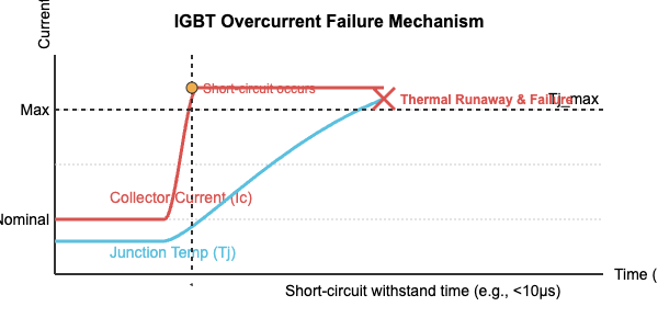
An overcurrent event occurs when the current flowing through the IGBT collector-emitter path exceeds the maximum rating specified in the datasheet. This can happen in two primary scenarios: a sustained overload or a catastrophic short-circuit.
- Overload: This happens when the load demands more current than the system is designed for over a prolonged period. While the IGBT might handle it for a few milliseconds, the excess current leads to a rapid increase in conduction losses (P_cond = Vce(sat) * Ic), causing the chip’s junction temperature to skyrocket beyond its safe limit.
- Short-Circuit: This is a far more violent event, caused by a phase-to-phase or phase-to-ground fault. The current rises almost instantaneously to many times the nominal rating. Even with a short-circuit withstand time of only a few microseconds (typically 5-10 µs for modern IGBTs), the immense power dissipation can cause localized melting of the silicon chip, bond wire lift-off, or even case rupture. A prime example of a robust module designed to handle tough conditions is the CM400DY-12NF, but even the best components require proper protection.
Physical Signature: Post-failure analysis of an overcurrent event often reveals melted or fused bond wires, a crater or burn spot on the silicon die, and sometimes carbonized residue within the module housing.
Overvoltage Failure: The Instantaneous Killer
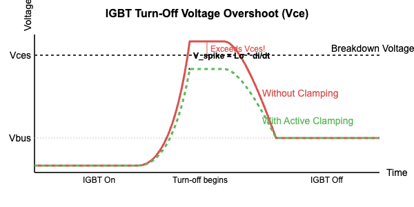
Overvoltage is a transient but deadly threat. It typically occurs during the turn-off phase of the IGBT. Due to parasitic stray inductance in the busbars and PCB layout, the rapid change in current (di/dt) induces a voltage spike across the collector-emitter terminals (V = L * di/dt). If this spike exceeds the IGBT’s breakdown voltage (Vces), the device can enter an avalanche breakdown mode.
When an IGBT experiences avalanche, it begins to conduct a large current in a small, localized area of the die. This creates an intense hot spot that can destroy the device in nanoseconds. Another, less common, overvoltage failure is on the gate-emitter (Vge). Exceeding the gate oxide’s maximum voltage rating (typically ±20V) will irreversibly puncture the gate oxide layer, leading to a loss of gate control.
Physical Signature: Overvoltage failure is harder to spot visually. It may leave a tiny, microscopic puncture in the silicon die. Gate-emitter failure often leaves no visible trace on the outside, but the device will fail to switch correctly when tested.
Overtemperature Failure: The Slow Death
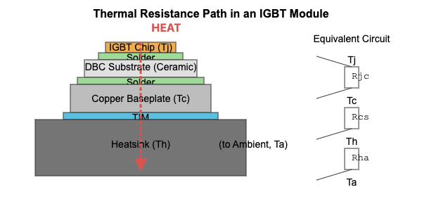
Overtemperature failure is often a long-term killer, resulting from inadequate Thermal Management. Every watt of power lost in the IGBT (both switching and conduction losses) is converted into heat. This heat must be efficiently transferred from the silicon chip to the ambient environment. If the thermal path is compromised, the junction temperature (Tj) will rise.
There are two main types of thermal failure:
- Exceeding Tj_max: A single event where the junction temperature surpasses the absolute maximum rating (e.g., 150°C or 175°C). This can happen during a sustained overload or cooling system failure, leading to immediate degradation or destruction.
- Thermal Cycling Fatigue: This is a wear-out mechanism. In applications like motor drives, the power output varies, causing the IGBT’s temperature to fluctuate. Each cycle of heating and cooling causes expansion and contraction of the different materials inside the module (silicon, copper, solder, ceramic). Over thousands or millions of cycles, this stress can cause solder layers to crack and bond wires to lift off the chip surface, leading to an increase in thermal resistance and eventual failure. This highlights the importance of understanding module construction and reliability data.
Physical Signature: Solder layer delamination and bond wire lift-off are the classic signs of thermal cycling failure, typically visible only through acoustic microscopy or cross-sectioning. Baseplate warping can also indicate severe overheating.
A Comparative Look at Failure Signatures and Mechanisms
For a quick diagnostic reference, this table summarizes the key characteristics of each failure mode. Understanding these differences is crucial for effective root cause analysis.
| Failure Mode | Primary Cause | Timescale of Event | Common Physical Signature | Key Datasheet Parameter |
|---|---|---|---|---|
| Overcurrent | Load short-circuit, phase fault, drive logic error | Microseconds (µs) to Milliseconds (ms) | Melted bond wires, burnt/cratered chip, carbonization | SCSOA (Short Circuit Safe Operating Area), Ic_max |
| Overvoltage | Stray inductance (Lσ) during turn-off, miller effect | Nanoseconds (ns) | Microscopic puncture in die, gate oxide breakdown (often invisible) | Vces (Collector-Emitter Breakdown Voltage), Vges (Gate-Emitter Voltage) |
| Overtemperature | Inadequate cooling, poor mounting, thermal cycling | Seconds to Years | Bond wire lift-off, solder layer fatigue/cracking, warped baseplate | Rth(j-c) (Thermal Resistance), Tj_max, Power Cycling Capability |
Proactive Prevention: From Design to Operation
Preventing failures is an exercise in disciplined engineering. It involves careful design, component selection, and operational monitoring. A comprehensive resource like The Engineer’s Ultimate Guide to IGBT Modules can provide a foundational understanding for these practices.
Mastering Overcurrent Protection
The key to overcurrent protection is speed. The protection circuit must detect the fault and safely turn off the IGBT before it self-destructs.
- Desaturation (Desat) Protection: This is the most common and effective method. It works by monitoring the IGBT’s collector-emitter voltage (Vce) during its on-state. If a short-circuit occurs, the current skyrockets, pulling the IGBT out of saturation, and Vce rises sharply. The gate driver IC detects this rise and initiates a “soft turn-off” to safely shut down the device without causing a massive overvoltage spike.
- Proper Gate Drive Design: The gate driver must supply the correct turn-on and turn-off voltages and have enough peak current capability to charge and discharge the IGBT’s gate capacitance quickly and effectively.
- Fuses: While semiconductor fuses can protect against longer-term overloads, they are almost always too slow to protect an IGBT from a short-circuit event. They should be considered system-level protection, not device-level protection.
Taming Voltage Spikes
Controlling overvoltage is all about minimizing stray inductance and managing the turn-off transient.
- Low-Inductance Busbar Design: The physical layout of the DC link capacitors to the IGBT module is critical. Use laminated busbars or wide, flat PCB planes to minimize the inductance (Lσ) of the commutation loop. Every nanohenry counts.
- Active Clamping: Advanced gate drivers incorporate active clamping features. If the driver detects Vce rising toward the breakdown voltage, it will partially turn the IGBT back on for a moment, creating a path for the current and actively clamping the voltage at a safe level.
- Snubber Circuit: An RCD (Resistor-Capacitor-Diode) snubber circuit can be placed across the IGBT to absorb the energy stored in the stray inductance and dampen the voltage overshoot. However, this adds complexity and losses.
Winning the War on Heat: Effective Thermal Management
A robust thermal design is non-negotiable for system reliability. The goal is to create an uninterrupted, low-resistance path for heat to escape.
- Heatsink Selection: The heatsink must be sized correctly based on the total power dissipation of the module and the maximum allowable ambient temperature. Perform thermal calculations or simulations to ensure the IGBT junction temperature remains well within the Safe Operating Area (SOA) under worst-case conditions.
- Thermal Interface Material (TIM): Never underestimate the importance of the TIM (thermal grease or phase-change material) between the module baseplate and the heatsink. Apply a thin, even layer to fill microscopic air gaps, which act as insulators. Using a high-quality TIM can lower Tj by 5-15°C.
- Proper Mounting: Always follow the manufacturer’s recommendations for mounting torque and sequence. Uneven pressure can warp the baseplate, creating gaps that drastically increase thermal resistance.
Practical Checklist for Enhancing IGBT Reliability
Use this checklist during your design and testing phases to systematically address the most common causes of IGBT failure.
- Gate Drive Validation: Are the turn-on (+Vge) and turn-off (-Vge) voltages stable and within datasheet specs under all load conditions?
- Dead Time Optimization: Is the dead time between high-side and low-side IGBTs sufficient to prevent shoot-through but short enough to minimize distortion?
- Overvoltage Measurement: Have you measured Vce overshoot at maximum current and bus voltage? Is there at least a 20% safety margin to Vces?
- Stray Inductance Check: Is the DC link layout as tight and low-inductive as possible?
- Desat Protection Test: Has the short-circuit protection circuit been tested and verified to trigger within the specified time?
- Thermal Calculation/Simulation: Has a worst-case thermal analysis been performed to ensure Tj remains within safe limits?
- Heatsink and TIM Verification: Is the heatsink properly sized? Is the TIM applied correctly? Is the mounting torque to specification?
- Component Selection: Does the selected IGBT module, like a dependable BSM200GB120DN2, have sufficient voltage and current ratings, including a comfortable margin for transient events?
Conclusion: Building Robust Systems Starts with Prevention
IGBTs are not fragile, but they operate at the limits of power density and switching speed. Their reliability is not solely dependent on the quality of the module itself but is a direct reflection of the quality of the surrounding circuit design and system integration. By understanding the mechanisms of overcurrent, overvoltage, and overtemperature failures, engineers can move from a reactive “fix-on-fail” approach to a proactive, prevention-focused design philosophy.
A robust design that meticulously manages these three stressors will not only prevent catastrophic failures but will also extend the operational life of the entire power system. When you need reliable components that form the foundation of such a design, exploring a wide range of vetted and tested IGBT modules is the critical next step in turning your robust design into reality.