The race to lower the Levelized Cost of Energy (LCOE) in the utility-scale solar industry is relentless. Every fraction of a percent in efficiency, every increase in power density, and every year added to an inverter’s lifespan is a hard-fought victory. As an engineer, I’ve spent years in the trenches of power system design, and I can tell you that many of these victories are won or lost in the heart of the solar inverter: the power module. It’s an unsung hero, silently switching thousands of times a second, bearing the full brunt of the sun’s power. Today, we’re moving beyond the standard 1000V systems and pushing into the 1500V DC frontier, a move that promises lower system costs but brings a new level of challenge. This is where a component like the Infineon FS450R17KE3 doesn’t just become an option; it becomes a critical enabler.
This isn’t just a datasheet deep-dive. This is a practical guide for engineers like Li Wei, who are on the front lines, tasked with designing that next-generation 250kW, 1500V string inverter. You know the pressure: boost efficiency, shrink the footprint, and guarantee 25 years of reliability in a harsh desert environment. Your core problem isn’t just picking a part number; it’s understanding how that choice will cascade through your entire design, from thermal management to gate drive complexity. Let’s tackle that head-on.
Why 1700V Modules are the New Benchmark for 1500V Systems
The first question is always, “Why a 1700V-rated IGBT for a 1500V DC bus?” The answer is reliability. A robust design requires a significant voltage safety margin to handle overshoots from switching transients and potential grid events. For 1500V DC systems, 1700V modules have become the industry-standard choice, providing that essential buffer. Attempting to use a 1200V module, like the venerable CM600DX-24T, would be courting disaster in a 1500V application. The move to 1500V systems is driven by economics; it allows for longer strings of solar panels, reducing combiner box and cabling costs, which ultimately lowers the overall installation price. However, this higher voltage places immense stress on the power switching stage, making the selection of a purpose-built module paramount.
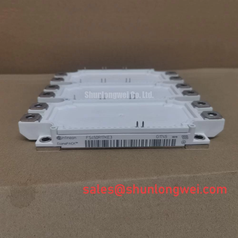
The FS450R17KE3 is a 1700V, 450A six-pack IGBT module housed in the well-established EconoDUAL™ 3 package. This configuration is ideal for building a standard three-phase, two-level inverter topology, which is common in string and central inverters. But its voltage and current ratings are just the beginning of the story.
Deconstructing the FS450R17KE3: What Matters for Solar Applications
When you’re designing a solar inverter, you’re balancing a triangle of trade-offs: conduction losses, switching losses, and thermal performance. How a module performs in these three areas dictates your inverter’s final efficiency and power density.
1. Loss Characteristics: The Efficiency Game
In a solar inverter, power losses are the ultimate enemy. The FS450R17KE3 utilizes Infineon’s Trench/Fieldstop IGBT3 technology, which was a significant step in optimizing the trade-off between saturation voltage (VCE(sat)) and switching energy (E_on, E_off).
- VCE(sat) – Conduction Loss: This module has a typical VCE(sat) of 2.15V at its nominal current. Lower VCE(sat) directly reduces conduction losses, which are dominant during periods of high, steady power generation.
- E_on & E_off – Switching Loss: At higher DC voltages like 1500V, switching losses become a much larger portion of the total loss budget. This is because the energy lost per switching event is proportional to the voltage. The FS450R17KE3 is engineered to offer moderate switching speed, which is a common compromise in high-voltage IGBTs. Pushing for extremely fast switching can lead to unacceptable voltage overshoots and EMI issues.
For a solar inverter that might operate at switching frequencies between 2.5 kHz and 8 kHz, balancing these two loss components is critical. Too much focus on minimizing VCE(sat) can lead to higher switching losses, and vice-versa. The IGBT3 technology in this module represents a balanced profile suitable for this application space.
2. Thermal Resistance (Rth): Keeping Your Cool
Efficiency losses manifest as heat, and effectively removing that heat is arguably the biggest challenge in power-dense inverter design. The datasheet specifies the junction-to-case thermal resistance (Rth(j-c)). For the IGBT in the FS450R17KE3, this is 0.058 K/W. A lower Rth value means the heat can escape from the semiconductor chip to the module’s baseplate more easily.
Why is this so critical for our engineer, Li Wei? A lower Rth allows for either:
- Higher Power Output: At the same maximum junction temperature (Tvj,max), you can push more current through the module.
- Smaller Heatsink: For the same power level, you can use a smaller, lighter, and cheaper cooling system.
- Increased Reliability: Operating the junction at a lower average temperature for the same power output significantly reduces thermal stress and extends the module’s power cycling lifetime.
The EconoDUAL™ 3 package is renowned for its robust mechanical design and effective thermal transfer, contributing to its widespread adoption in demanding applications like solar and wind power.
Critical Design Considerations Beyond the Datasheet
Selecting the module is step one. Successfully integrating it is the real engineering challenge. Here are the key areas to focus on for a robust 1500V inverter design using the FS450R17KE3.
Gate Drive Design: The Key to Control and Protection
At 1700V, the gate drive circuit is not a place to cut corners. A poorly designed gate drive can lead to insufficient turn-on (increasing conduction losses), slow turn-off (increasing switching losses), or catastrophic failure from parasitic turn-on.
- Isolation: The high bus voltage necessitates a driver with reinforced isolation. The driver’s power supply must also be rated for this high isolation voltage to ensure safety and reliability.
- Negative Gate Voltage: Using a negative gate voltage (e.g., -8V or -15V) during the off-state is highly recommended. This provides a larger margin against the Miller effect causing parasitic turn-on, especially given the high dv/dt rates in 1500V systems.
- Desaturation Protection: A fast and reliable short-circuit (desaturation) protection is mandatory. The FS450R17KE3 has a short-circuit withstand time of 10µs. Your gate driver must detect the desaturation condition and safely shut down the IGBT well within this timeframe. Companies like CONCEPT (now part of Power Integrations) offer plug-and-play drivers like the 6SD312EI which are specifically matched for this module.
Layout and Busbar Design: Taming Stray Inductance
Stray inductance in your DC link busbar is your worst enemy. During IGBT turn-off, this inductance (Lσ) creates a voltage overshoot (V = Lσ * di/dt) that adds to the DC bus voltage. In a 1500V system, this can easily push the collector-emitter voltage beyond the 1700V limit, destroying the module. A low-inductance, laminated busbar design is not just good practice; it’s a necessity. The symmetrical layout of the EconoDUAL™ 3 package helps in designing a parallel-path, low-inductance connection.
Package and Mounting: A Nod to the Future
The FS450R17KE3 comes in a package with screw terminals for power connections and PressFIT pins for control signals. The PressFIT technology offers a reliable, solder-free connection to the control board, which simplifies manufacturing and improves long-term reliability by eliminating a potential point of failure. When comparing module options, consider the package technology. For instance, some Semikron modules like the SEMIX453GB176HD utilize spring contacts for the control signals, another solder-free approach. The choice between screw, solder, press-fit, or spring contacts can have significant impacts on your assembly process and mechanical design.
Conclusion: Making the Right Choice for the Next Generation
For an engineer developing a high-performance 1500V solar inverter, the Infineon FS450R17KE3 represents a solid, mature, and reliable choice. It provides the necessary voltage headroom for 1500V DC systems and features a well-balanced loss profile thanks to its proven IGBT3 technology. Its housing in the industry-standard EconoDUAL™ 3 package ensures robust thermal and mechanical performance.
However, the module itself is only half the solution. Realizing its full potential requires a holistic design approach that pays meticulous attention to the gate driver, DC link layout, and thermal management. By understanding the interplay between the module’s characteristics and the surrounding system design, you can overcome the challenges of high-voltage operation and build a solar inverter that is not only efficient but will reliably generate clean energy for decades to come.
Are you tackling the challenges of a 1500V design or looking to optimize your power module selection? Explore our full range of IGBT modules for solar applications or contact our team of application engineers to discuss your specific requirements. Let’s build the future of energy, together.