

Content last revised on September 10, 2026
Incoming Inspection and Compatibility Verification
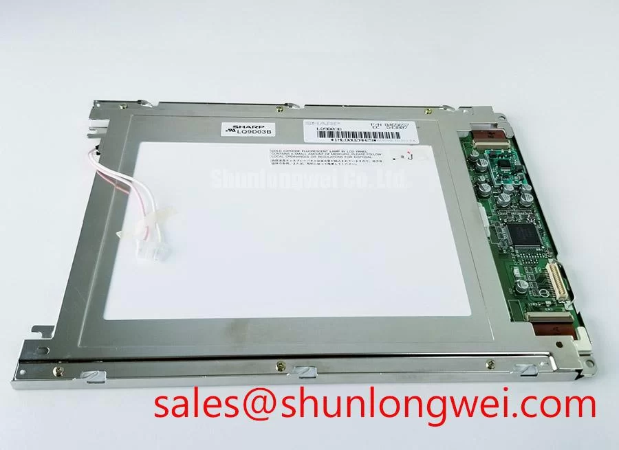
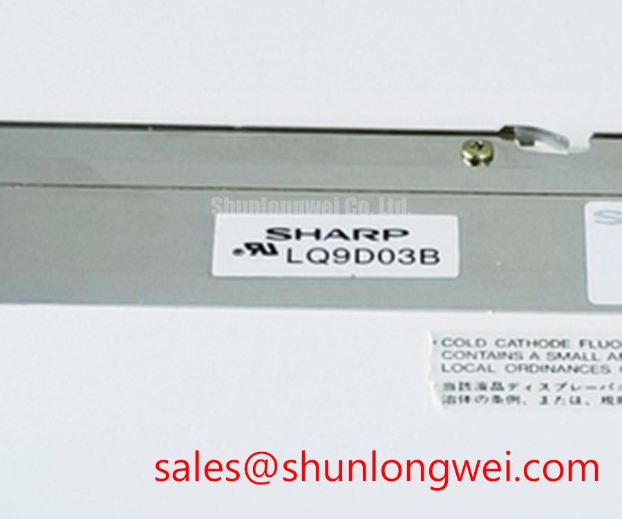
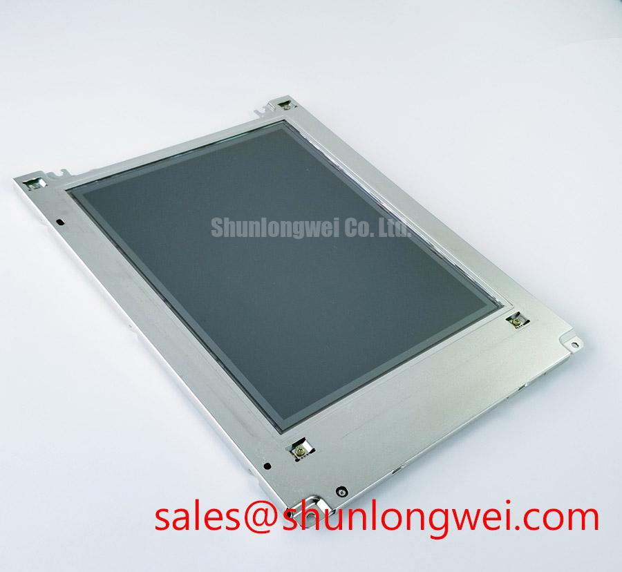
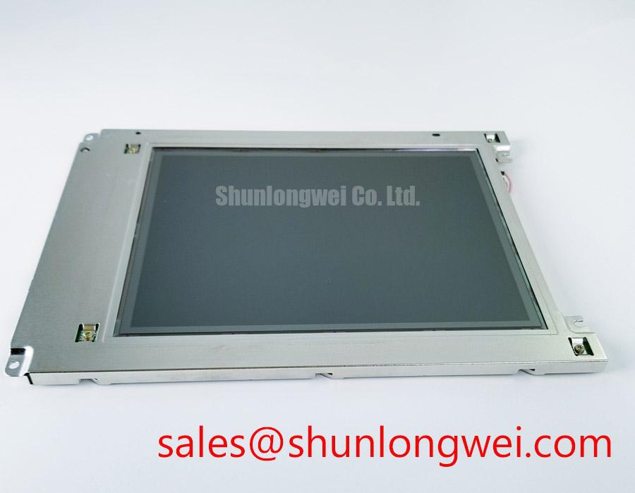
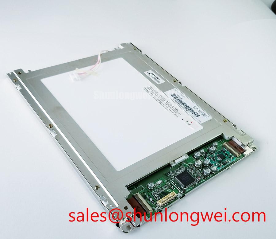
Where the assembly provides accessible ground and shield points, measure the panel’s ground lug to outer shield resistance with a four-wire milliohm meter before applying system power, then inspect the bezel, connector area, and visible surface for transport damage. For the Sharp LQ9D03B, this incoming QA check should be recorded alongside the original equipment interface documentation because the supplied product data does not confirm the complete host pinout, backlight architecture, touch technology, optical coating, or environmental rating.
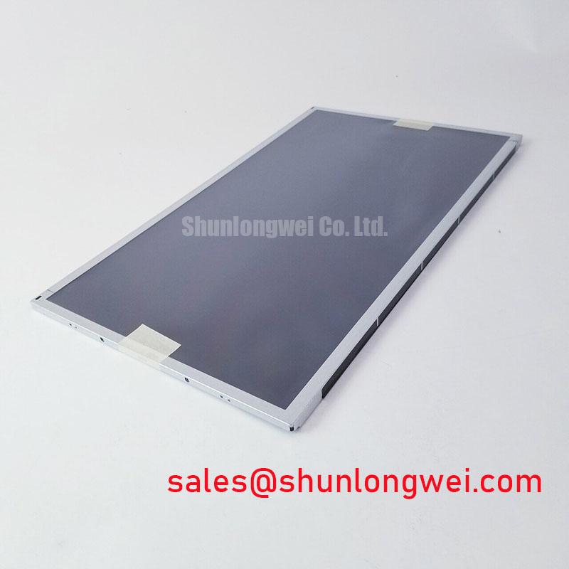
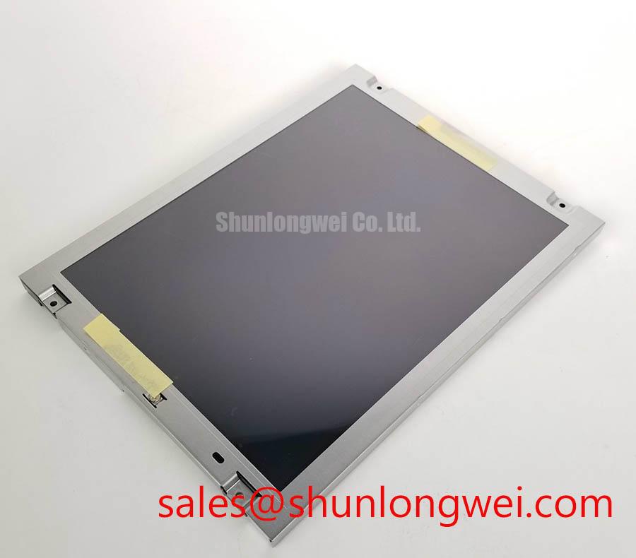
The LQ9D03B is evaluated here as an industrial LCD display replacement candidate for equipment such as a harsh marine radar or navigation bridge console. The documented mechanical and interface values support a disciplined inspection process, but they do not by themselves establish system compatibility. Designers should verify the original panel documentation, cable assembly, supply rail, timing configuration, backlight driver requirements, mounting envelope, and sealing arrangement before installation.
| Parameter | Documented value | Classification and verification |
|---|---|---|
| Chassis diagonal warp tolerance | ≤ 0.3 mm | Stated product-data value. Verify with an optical profilometer across a four-point datum plane. |
| Bezel gasket compression deflection | 25% to 30% nominal | Design Consideration. Verify with a calibrated depth micrometer at eight perimeter clamping points. |
| Ground lug to outer shield resistance | < 0.1 Ω | Incoming Bench QA Measurement at 100 mA DC using a four-wire Kelvin milliohm meter. Confirm that the panel provides the stated grounding points. |
| Differential interface line impedance | 100 Ω ± 10% | Design Consideration for compatible differential interconnects. Verify with TDR using a rise time of ≤ 35 ps where applicable. |
| Differential intra-pair skew budget | ≤ 50 ps | Engineering Calculation. Verify with a multichannel high-bandwidth real-time oscilloscope. |
| Logic-rail current | Record IDD under the documented supply conditions; no fixed current value is supplied | Measurement baseline. Confirm the required rail and measurement conditions from the original panel documentation before testing. |
Verifying Backlight Drive, PWM, and EMI Behavior across 200 Hz to 1 kHz
Do not assume a replacement panel uses the same backlight driver topology as the removed unit. The available LQ9D03B information does not identify a CCFL cold ignition circuit, an LED array, a constant-current driver, a PWM input, or a specified dimming ratio. A repair engineer should first identify the host system’s backlight connector and driver board, then compare the original wiring and control signals with the replacement panel documentation.
For a legacy display assembly using high-voltage CCFL ignition, the stated 1500 V to 1650 V RMS range belongs to an application evaluation question rather than a confirmed LQ9D03B rating. A constant-current LED arrangement must be treated in the same way unless its electrical limits are documented for this exact model. Connecting a driver solely because the connector appears mechanically similar can expose the panel to an unsuitable ignition, current, or fault response.
When the host system uses PWM dimming between 200 Hz and 1 kHz, designers should verify duty-cycle linearity, visible flicker, conducted noise, radiated coupling, and audible behavior at the selected operating point. These are system-level design considerations, not factory specifications for the LQ9D03B. An oscilloscope probe should be placed at the driver interface and at the panel side of the cable where practical. Correlate the waveform with image brightness and any interference observed on radar graphics, navigation overlays, or touch coordinates.
Backlight open-circuit and short-circuit protection also require verification at the driver level. A fault response may involve shutdown, retry, current limiting, or a host alarm, but the available product data does not define which behavior applies to this panel. During bench work, current should be limited by the test setup, and the engineer should confirm whether the existing driver detects an open load or a shorted load without exceeding the panel’s documented electrical boundary.
The frequently quoted 1000:1 PWM dimming figure and 50,000-hour half-brightness figure are not included in the supplied LQ9D03B specification set. They must not be presented as this model’s guaranteed performance. If a marine console requires a particular brightness lifetime, the complete display and backlight data should be obtained and assessed under the actual thermal, vibration, salt atmosphere, and duty conditions.
Incoming Benchtop Inspection: COG and TAB ACF Integrity
Begin the optical inspection with a clean, controlled test image and a low ambient light level. A practical three-stage sequence is full white, full black, and primary color fields. White reveals dark or inactive pixel areas, black reveals bright leakage and nonuniform regions, while red, green, and blue fields help separate color channel defects from general illumination problems. The sequence is an inspection method, not a substitute for the manufacturer’s pixel acceptance criteria, which are not provided here.
A 45-degree flashlight inspection can help locate a shadow that changes with viewing angle. If the shadow tracks the perimeter or diffuser area, inspect the bezel pressure, frame seating, and backlight path. If a narrow line remains fixed at a glass edge or connector region, inspect the cable seating and the visible bonded interface without applying pressure to the panel. This observation may indicate a display-signal or bond-related issue, but it does not prove a particular internal failure mode.
COG and TAB bonding areas should be checked for lifted edges, visible contamination, uneven contact pressure, and cable insertion that is not square to the connector. Do not bend the glass or use a probe to press on a bonded region. A no-image condition should be separated into host output, cable continuity, panel logic supply, backlight operation, and image data path checks. The supplied data identifies an IDD measurement baseline, but it does not provide a fixed current value or a complete pin assignment.
For differential signaling, a TDR assessment of 100 Ω ± 10% is a Design Consideration for bridge interconnects. The stated measurement method uses a step with rise time of ≤ 35 ps. In a repair environment, compare the suspect cable and panel path with a known-good assembly where available. Excessive discontinuity, connector stub length, cable deformation, or shield termination changes may produce eye closure or unstable image data. The intra-pair skew budget of ≤ 50 ps is identified as an Engineering Calculation and should be confirmed against the actual system timing margin rather than treated as a universal replacement guarantee.
💡 Bench Tip: Use ESD protection and insert every flat-flex cable squarely, with the contacts fully aligned before locking the connector.
Backlight degradation should also be handled carefully. The supplied data does not certify an LED half-life, a CCFL life curve, or an MTBF value for the LQ9D03B. A measured brightness decline may be influenced by driver current, temperature, optical contamination, aging, and measurement geometry. Record the instrument, viewing angle, test pattern, and operating condition if a baseline is created. Do not convert one incoming inspection result into a predicted field life without an applicable manufacturer or standards-based source.
For replacement planning, engineers may assess the similarly categorized LM057QC1T08 as a separate compatibility reference. It should not be treated as an automatic substitute. Mechanical dimensions, signal protocol, supply voltage, backlight control, mounting points, and image timing must be compared against the original assembly.
Preventing Localized Light Guide Plate Compression Warp on Dark Screen Fields
Dark-field inspection is especially useful after the panel is installed in a metal console bezel. Display the full black pattern, allow the assembly to reach a stable operating condition, and inspect from the intended operator viewing position. A bright patch, crescent, or corner shadow can result from bezel contact, uneven gasket loading, frame distortion, cable pressure, or backlight nonuniformity. The visual symptom alone does not identify the responsible part.
The stated chassis diagonal warp tolerance is ≤ 0.3 mm, verified by optical profilometer scanning across a four-point datum plane. This value should be checked before clamping a replacement into a preloaded enclosure. If the enclosure is twisted, measuring only the loose panel may not represent the installed condition. A second inspection after fastening can reveal whether the mounting structure changes the panel plane.
The supplied bezel gasket value of 25% to 30% nominal compression deflection is a Design Consideration, not a confirmed installation guarantee for every host chassis. Measure the compression at the perimeter rather than assuming that equal fastener rotation creates equal pressure. Seal design, gasket hardness, frame flatness, and enclosure tolerances remain system-controlled. A marine bridge console may also require sealing against spray and salt contamination, but the LQ9D03B data supplied here does not establish an ingress rating or salt-fog qualification.
Cross-pattern tightening can help distribute load, but the correct fastener torque must come from the enclosure and fastener design documentation. The supplied product information does not authorize a fixed M3 torque value. Engineers should prevent local point loading, keep hardware clear of the active area, and verify the optical result after the panel reaches its normal operating condition. The same check is useful after cable routing because a tightly folded cable can transfer force into the connector or frame.
Surface glare and outdoor readability must be verified from the actual panel sample. AG or AR treatment, contrast ratio under direct sunlight, and a specified illuminance performance value are not documented for this LQ9D03B record. If the target console is exposed to strong daylight, test reflected glare, black level, white level, viewing angle, and operator readability with the final window, gasket, hood, and cover installed. Do not describe the panel as anti-glare or sunlight-readable unless the applicable optical specification confirms it.
Mitigating Gray-to-Gray Response-Time Escalation during Cold-Start Machine Power-Up
Cold-start evaluation should begin with the host power sequence and the panel’s documented logic-rail requirement. The supplied information refers to an IDD nominal bench baseline but gives no fixed current value. The system integrator should verify the required supply voltage from the original panel documentation rather than selecting between rails by appearance or connector position.
At power-up, observe the logic rail, enable signals, image data, and backlight behavior together. A delayed image may relate to host sequencing, cable initialization, panel logic startup, temperature, or a backlight interlock. A changing IDD reading can guide the next measurement, but it is not sufficient to diagnose a bond, timing, or liquid-crystal fault. Compare the startup waveform with a known-good panel and check whether the host continues sending valid image data while the screen remains dark.
Liquid-crystal response can vary with temperature, but the supplied LQ9D03B information does not specify a Gray-to-Gray response time, operating temperature range, cold-start limit, thermal-cycle qualification, or perimeter sealant performance. The proposed evaluation range of −30°C to +85°C must therefore be treated as a system test condition, not as a confirmed product rating. Any cold-chamber test should use controlled ramping, monitored supply conditions, and an image sequence that exposes slow transitions without confusing them with source frame timing.
Signal integrity remains relevant during cold start. Verify differential line impedance against the 100 Ω ± 10% Design Consideration where the host uses a compatible differential interface, and assess intra-pair skew against the ≤ 50 ps Engineering Calculation budget. The complete panel interface protocol is not supplied, so LVDS, TTL, connector pinout, lane mapping, and clock polarity must be confirmed from the original documentation. If the panel uses another interface, these checks may not apply.
For broader display interface principles, the engineering team can consult The Ultimate Guide to Industrial TFT LCD Technology. Use that material as a technical reference while keeping the LQ9D03B acceptance decision tied to the documented values, the original equipment requirements, and measured behavior of the installed assembly.
Before release to service, repeat the full color-field check, confirm the shield-resistance measurement, inspect the connector locks, and document any host-specific backlight or touch-interface requirements. Capacitive or resistive touch operation, glove sensitivity, water response, AG or AR coating, and EMC compliance of the complete console require separate system verification because they are not stated as factory parameters for the LQ9D03B.