

Content last revised on September 10, 2026
Full-Screen Primary Color AOI Screening: Stuck Sub-Pixels & Background Uniformity Audit
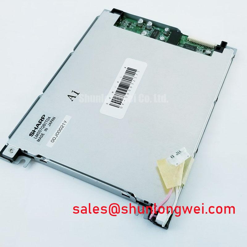
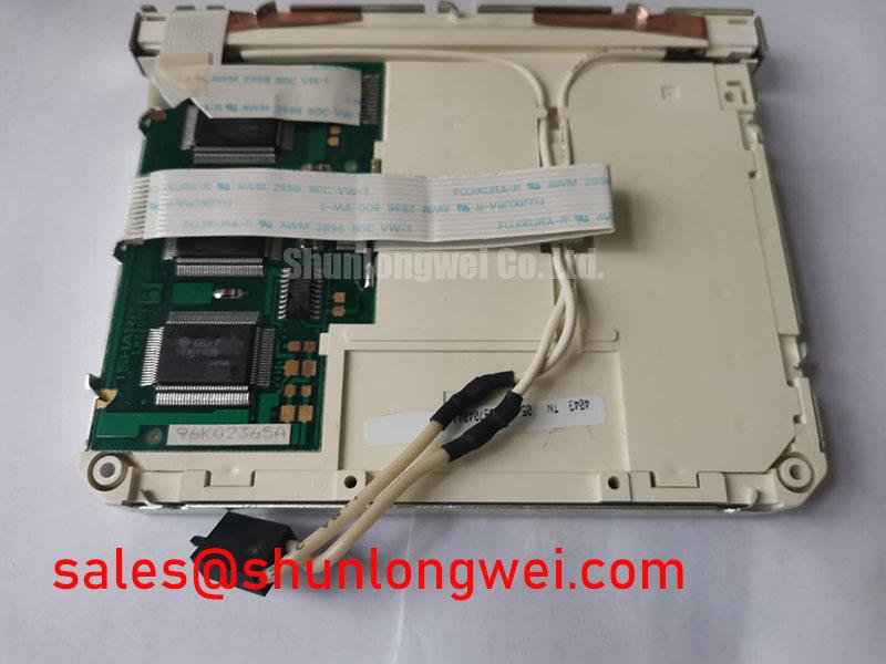
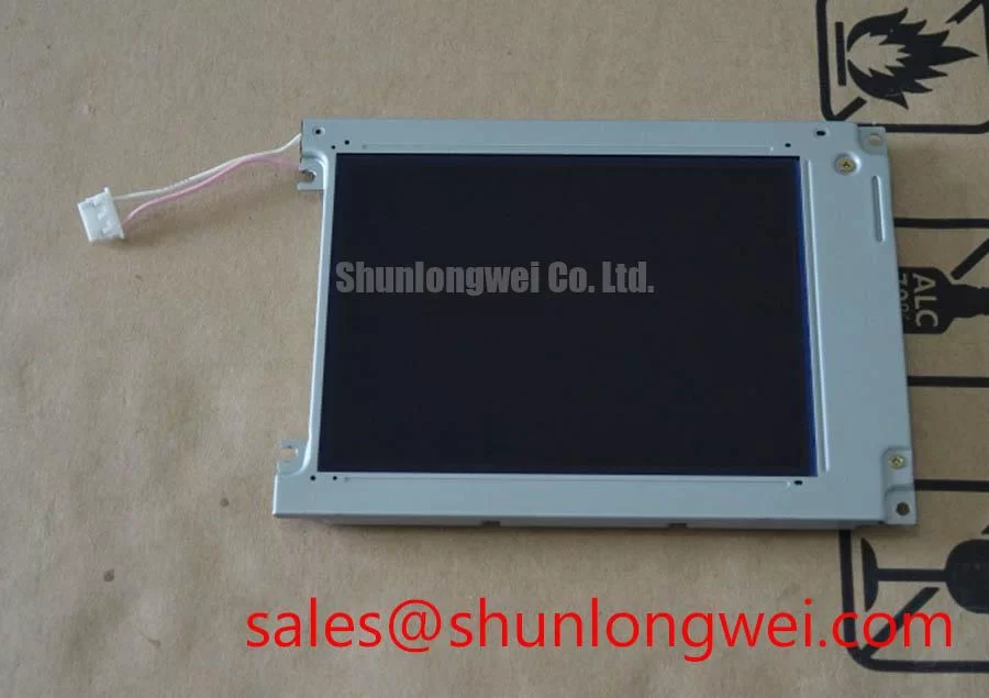
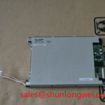
With power removed, inspect the LM057QC1T08 display face, perimeter, connector area, and rear assembly for cracks, pressure marks, contamination, loose cables, or signs of mechanical stress before reconnecting the original equipment harness. This Sharp panel is a 5.7 inch CSTN transmissive LCD with a 320(RGB) × 240 QVGA active area, using 8 bit parallel CMOS data and a single CCFL backlight with integrated inverter.
For a bench inspection, bring the host controller up with stable display timing and present full screen black, white, red, green, and blue patterns. Observe each image at normal viewing distance first, then inspect the active area more closely for persistent bright points, dark points, color shifts, vertical lines, horizontal bands, or uneven regions. A defect that remains in the same physical location through all color patterns deserves separate attention from image defects that move or change with the displayed data.
When the screen appears dark but the equipment is otherwise operating, use a flashlight at an oblique angle across the front surface. A faint image under external light can indicate that the display data path is still active while the illumination path requires investigation. A completely blank field can involve the source board, the parallel data connection, supply sequencing, or the panel itself. These observations are diagnostic direction only; they do not establish a single failure cause.
The official optical specification lists 120 cd/m² typical luminance and a 25:1 contrast ratio. These values describe the panel specification and should not be treated as a guaranteed measurement after installation behind an added window, touch overlay, protective film, or aging system optics. The supplied display specification also identifies a standard polarizer hard coating. Any anti reflective cover glass or direct optical bonding should be evaluated as an enclosure level integration decision rather than assumed to be included with the panel.
The stated backlight life reference is 20,000 hours typical to half brightness. It is a manufacturer specification reference for the backlight assembly, not a prediction of remaining operating hours in a particular CNC operator panel or robot teach pendant. Brightness loss should be evaluated against a known good panel, the host backlight control condition, and the actual viewing environment.
The requested inspection method should avoid attributing line defects to unverified internal constructions. A fixed line may be associated with panel drive circuitry, interconnect stress, timing integrity, or host video data. Compare the panel with the original known good signal path where possible. If a line disappears after reseating the cable or repairing a connector latch, the cable path becomes a practical focus. If it persists with controlled image patterns and a verified signal source, the display assembly requires further evaluation.
⚠️ Field Alert: Disconnect equipment power and allow stored energy to discharge before inserting or removing the panel cable, because live connection can expose signal contacts to unintended voltage levels.
PWM dimming frequency, duty cycle behavior, audible noise limits, and visible flicker performance are not specified factory parameters for the LM057QC1T08. Where the host equipment provides a dimming or enable signal, this is a Design Consideration: verify the controller waveform and backlight response in the finished equipment under the intended operating conditions, rather than applying a generic frequency setting.
Shielded FFC/FPC Flat Flexible Cable Grounding across 360-Degree Connector Shells
Before treating display noise as a panel issue, reseat the original interface cable and inspect both connector latches under magnification. The LM057QC1T08 accepts 8 bit parallel data with CMOS logic. Its documentation does not identify an LVDS interface, so an LVDS cable, LVDS pinout, or LVDS termination scheme must not be assumed for this model. The system integrator should verify the original panel documentation and host board schematic before any cable substitution or adapter design.
Pixel shimmer, unstable color regions, or horizontal noise bands near a motor drive can arise from several paths: imperfect connector contact, cable damage, a disturbed return path, supply ripple, controller timing, or conducted and radiated interference from nearby equipment. Start with physical checks. Confirm that the connector is fully seated, that the locking feature engages correctly, and that cable routing has not created a tight bend or abrasion point. Inspect the host display connector as carefully as the panel connector; an apparently good panel cannot correct a compromised mating contact.
Shielding around a flexible display cable is a Design Consideration, not an official feature claim for this Sharp display. If the original equipment uses a shielded cable or grounded connector shell, retain the equipment manufacturer’s grounding arrangement during repair. Any change in shield termination should be evaluated at the machine level because chassis layout, power supply construction, drive switching behavior, and cable route determine the result. A shield connected incorrectly can alter the noise path rather than remove it.
Common mode ferrite components can be evaluated where system measurements show conducted or radiated noise coupling into the display cable. Their selection is system determined. Verify image stability with the drive inactive and active, compare the result against a known good cable path, and avoid adding components simply because a particular motor drive is present. No independent EMC certification claim is made for the display panel.
The supplied engineering context identifies a target bus line capacitance of less than 30 pF for matching the parallel data bus. Treat this as an integration target, not as permission to alter cable length or loading without validation. Parallel display buses depend on the relationship between source drive strength, cable construction, line capacitance, return path continuity, and timing margins. When a replacement installation has visual instability, inspect the original harness and verify signals at the host side and panel side with suitable test equipment against the known good signal path.
For an industrial automation CNC operator panel or robot teach pendant, maintain physical separation between display wiring and high energy switching conductors where the equipment layout permits. The purpose is to reduce coupled noise into the data and control path. The acceptable routing, shielding, and grounding arrangement must be confirmed by the equipment system designer through switching tests in the actual enclosure.
Engineers comparing physical display formats may also review the LQ9D03B as a same size class and QVGA reference. This is a comparison reference only. Mechanical dimensions, connector assignment, timing, electrical rails, optical behavior, and backlight implementation must be checked independently before considering any replacement path.
Diffuser Film & Prism Sheet Thermal Buckling Prevention under Continuous Full-Duty Operation
The LM057QC1T08 is specified with one CCFL backlight and an integrated inverter; it is not specified as an LED backlight panel. Therefore, LED diffuser architecture, prism sheet construction, LED constant current efficiency, L70, B50, and a 50,000 hour LED lifetime are not official characteristics of this model and should not be used to judge its condition.
When a panel is installed in a continuously operating machine interface, inspect the surrounding enclosure rather than assigning optical changes to a specific unverified internal material. Check whether nearby power assemblies, inadequate airflow, direct sunlight, or enclosure compression are exposing the display area to abnormal thermal stress. Also inspect the bezel for uneven pressure. A tightly constrained window or mounting frame can create visible nonuniformity, especially when the panel is warm, even if the image data is correct.
Adding aluminum spreader rails, thermal pads, or other mechanical heat paths is a Design Consideration. The intended benefit is to avoid concentrated heating around the display perimeter when the equipment enclosure creates localized hot spots. Whether these measures are appropriate depends on the original mounting arrangement, allowable panel contact areas, clearances, vibration exposure, and measured temperature behavior. The system designer should validate that an added mechanical part does not place bending load on the display or interfere with cable routing.
On a repair bench, compare the display after cold power up and after the host machine has reached its normal operating condition. Note changes in brightness, shadowing, color balance, or screen uniformity without declaring a cause from appearance alone. If the issue is temperature dependent, verify the supply rails and backlight behavior under the same condition. If the visual effect remains while the panel is driven by a controlled source, the display assembly can be isolated more reliably from host controller effects.
The front surface reflectance context supplied for this platform references a standard polarizer hard coating and a value below 1.5% when an optical bonded anti reflective cover glass is used. This reduced reflectance condition belongs to the stated optical bonding target, not necessarily to an unmodified panel installation. A resistive overlay, projected capacitive overlay, or infrared bezel is likewise an external integration choice. The supplied touch comparison indicates that resistive touch can reduce effective brightness, while projected capacitive touch and infrared bezel systems have different optical and maintenance implications. None of those touch technologies should be represented as an included feature of the LM057QC1T08 without confirmation from the original equipment build.
For equipment intended for extended service, Industrial Display & HMI Solutions provides broader context for evaluating enclosure conditions, interface integrity, and display integration. The panel level decision should remain anchored to the actual Sharp specifications, the original machine documentation, and measurements taken from the installed system.
Dual-Channel CCFL High-Voltage Resonant Inverter Striking Voltage & Ignition Debugging
Begin CCFL diagnosis by confirming that the host equipment reaches its intended display power state and that the panel cable is seated before attempting any measurement around the backlight section. The official configuration for the LM057QC1T08 is one CCFL with an integrated inverter. It is not a dual channel CCFL specification. The supplied documentation does not state a CCFL striking voltage, operating voltage, lamp current, inverter frequency, open lamp shutdown threshold, short circuit threshold, or a diagnostic fault output. These values must not be invented or transferred from a different display family.
A dark display can be approached methodically. First verify whether an image is present using the angled flashlight check. Next confirm the host supply condition and display control state according to the original equipment documentation. Inspect cable engagement, connector damage, and signs of arcing or heat discoloration around the system connection points. If the image is present but illumination is absent, the panel backlight path, host power delivery, control logic, and the integrated inverter all remain possible investigation areas.
Because the inverter is integrated, its serviceability and measurement points are governed by the panel construction and original equipment design. High voltage probing should only be performed by qualified personnel using equipment rated for the expected measurement environment and a safe test procedure. A general probe method or a target ignition voltage cannot be prescribed from the available official specifications. Do not connect an arbitrary external CCFL inverter to the panel, because lamp characteristics, connector assignment, isolation requirements, and control sequencing have not been confirmed.
The contrast between CCFL and LED systems is useful only when it remains factual. This Sharp panel uses CCFL illumination, while a different LED panel would require its own verified driver characteristics and lifetime data. Constant current LED driver operation, high ratio PWM dimming, and long LED lifetime claims do not describe the LM057QC1T08. For this model, use the official 20,000 hours typical backlight life reference to half brightness as the relevant backlight life statement, subject to actual operating conditions.
If a machine shows intermittent illumination, avoid assuming that a buzzing sound, a flicker event, or a dark screen identifies one failed part. Observe whether the condition changes with cable movement, host power cycling, equipment temperature, or load state. Compare with a known good display assembly where the original system design permits. This separates repeatable panel related behavior from controller, cable, or power distribution effects without relying on unsupported diagnostic thresholds.
For a CNC operator panel or robot teach pendant repair, confirm the complete compatibility set before fitting a replacement display: model marking, 5.7 inch active display class, 320(RGB) × 240 QVGA format, CSTN transmissive technology, parallel CMOS interface, original connector arrangement, mechanical fit, and the CCFL backlight arrangement. The original equipment documentation determines supply rails, power sequencing, mounting method, touch interface presence, and any dimming control behavior.