Content last revised on September 3, 2026
Surface Anti Glare and Anti Reflective Evaluation for High Ambient Readability
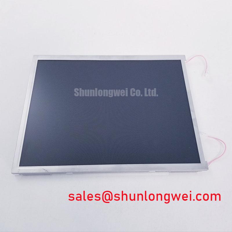
Begin incoming inspection of the LQ150X1DWF1 by checking the TFT LCD display module face, perimeter, connector area, and flex-cable seating under diffuse white illumination before applying power. This Sharp industrial-grade LCD/HMI panel should be evaluated as an assembly: visible surface condition, connector integrity, displayed image uniformity, and compatibility with the original equipment documentation all matter during repair assessment.
The available official factory information identifies LQ150X1DWF1 as a Sharp TFT-LCD Display Module in the Industrial Grade LCD/HMI Panel category. Supply requirements, interface assignment, timing, optical limits, backlight configuration, environmental ratings, and mechanical dimensions should be verified from the original panel documentation and against the removed display before replacement work begins.
| Model | LQ150X1DWF1 |
| Manufacturer | Sharp |
| Product Category | Industrial Grade LCD/HMI Panel |
| Module Type | TFT-LCD Display Module |
| Identification Status | Model and category identified from available factory information |
Start the optical check with a full-screen white pattern, followed by black, red, green, and blue patterns. A uniform white field helps reveal localized dim areas, pixel clusters, coating marks, pressure patterns, and perimeter light irregularities that can be missed when the display is showing application graphics. A black field is useful for identifying unwanted glow, uneven dark appearance, and reflections from the inspection environment.
High ambient readability is not determined by brightness alone. Surface reflections, enclosure window reflections, image contrast, viewing angle, and the optical characteristics of the original panel all influence whether operators can read status text and alarms. The official information provided for LQ150X1DWF1 does not state an anti-glare coating, anti-reflective treatment, contrast ratio, luminance rating, or viewing-angle specification. These properties should therefore be checked against the original Sharp documentation rather than assumed from the panel category.
For a repair bench, place the panel behind the same type of protective window used by the equipment whenever possible. A panel that appears acceptable without the front window may show objectionable reflections once installed. This matters when evaluating displays used in industrial HMI equipment, passenger information terminals, or cab signalling interfaces, where clear character recognition can be more important than an attractive image under laboratory lighting.
Design Consideration: if the host controller uses pulse-width modulation for backlight control, the panel integrator should verify the dimming waveform, duty-cycle behavior, and visual stability with the actual display assembly. PWM operation in the general 200 Hz to 1 kHz range is commonly evaluated for visible flicker and possible acoustic interaction with surrounding equipment, but it is not an official specification of the LQ150X1DWF1. The correct operating method is determined by the original backlight circuit and should be confirmed by system testing.
TN, IPS, and MVA are different LCD mode families with different off-axis behavior. No display mode, grayscale inversion characteristic, or full viewing cone is confirmed here for this Sharp model. Do not classify the LQ150X1DWF1 by panel technology from an image alone. View the panel from the expected installed angle while showing fine text, grayscale bars, and primary-color fields, then compare it with the equipment’s known-good display path.
Where a hardware replacement evaluation is required, LMS700KF01-001 can be reviewed as a separate display-module reference. Mechanical fit, active area, electrical interface, power sequence, timing, mounting points, and optical behavior require independent verification; a similar category description does not establish direct interchangeability.
FFC/FPC Cable Grounding and Connector-Shell Noise Control
Horizontal noise bands, intermittent pixel disturbance, unstable colors, or image movement should first be investigated at the complete signal path: controller output, display cable, connector engagement, panel grounding arrangement, and nearby switching equipment. Before replacing a panel, inspect whether the flex cable is fully inserted, square to the connector, free from creases, and locked according to the connector design. A cable that is slightly skewed can create faults that resemble a failing display.
In cabinets containing servo drives, variable-frequency drives, relays, contactors, or switched power supplies, common-mode noise can couple into display cables. Design Consideration: use the original cable shielding and grounding architecture where available, maintain a continuous low-impedance shield path through the connector shell where the equipment design provides one, and keep the display signal route separated from high-energy motor conductors. Ferrite components can be assessed where system measurements identify common-mode interference, but their placement and impedance selection must be validated on the installed equipment.
The official information supplied for the LQ150X1DWF1 does not identify a TTL interface, LVDS interface, pin assignment, transmitter-clock limit, data hold-time requirement, or connector-shell grounding requirement. The system integrator should verify the required supply voltage, interface standard, pinout, timing, and power sequencing from the original panel documentation. Connecting an unknown interface standard to a replacement panel can cause a blank screen, corrupted image, or electrical damage.
💡 Bench Tip: Disconnect power, use appropriate ESD protection, and lock the display cable only after confirming that the flex is flat, fully aligned, and seated evenly across the connector.
When image artifacts occur near motor-drive operation, compare the display with the drive disabled and enabled while observing the original signal route. If an oscilloscope is available, engineers should compare clock and data behavior against a known-good signal path. A changing waveform or degraded signal margin may indicate cable routing, termination, grounding, or controller-output issues, while a stable incoming signal with persistent panel-local artifacts calls for further panel assessment.
Backlight supply circuitry also deserves separate inspection. A display may receive valid image data while the illumination path is inactive or unstable. The Sharp module should only be operated with the power topology specified by the original equipment documentation. For related display-system evaluation, LQ150X1LG11 is available as a separate Sharp panel reference, but it must not be treated as confirmation of the LQ150X1DWF1 backlight or interface configuration.
Flashlight Dark Shadow Optical Diagnostic for Logic and Backlight Isolation
A controlled flashlight inspection is useful when a screen appears black or unusually dim. First, verify that the host system is issuing its expected display command and that the panel connection is secure. Next, present known primary-color and grayscale patterns if the controller remains operational. Then direct a flashlight across the viewing surface at roughly a 45-degree angle while observing for a faint image. This approach can help separate an image-generation issue from an illumination-path issue without making unsupported assumptions about the cause.
If a faint but structured image is visible under external light, the observation may suggest that the image path is active while the backlight path requires investigation. Inspect the original equipment’s backlight enable control, supply connector, cable condition, and protection behavior according to the equipment service information. If no image appears, investigate the controller output, cable continuity, connector contact, power sequence, and panel response as a connected system.
Persistent lines, column-like disturbances, color changes, or broad bands should be documented with photo evidence on white, black, red, green, and blue fields. Their appearance can vary with temperature, cable position, pressure around the frame, or incoming video content. Avoid assigning a single cause from one image. Repeat the observation after reseating the cable, removing external mechanical stress, and comparing with a known-good controller or panel where available.
The supplied factory information does not confirm a contrast-ratio value, sunlight readability rating, anti-glare optical rating, backlight lifetime, or a 50,000-hour performance figure for the LQ150X1DWF1. Claims about optical endurance or brightness retention should be based only on the relevant Sharp specification or documented equipment test data. For field repairs, recording the observed brightness balance and image behavior before and after installation provides more useful evidence than relying on generalized lifetime estimates.
Where the installed terminal must work under strong cabin or station lighting, engineers can use the equipment enclosure, window condition, and ambient reflections as part of the inspection. A dim image can be caused by many interacting factors, including the host brightness command, backlight supply behavior, window contamination, surface reflections, or panel condition. This practical approach supports evaluation without representing unverified optical values as factory ratings.
Temperature Operational Margin Assessment
Before evaluating the LQ150X1DWF1 for a cold or hot location, confirm its official operating and storage temperature limits from the original Sharp documentation. The range from minus 30°C to plus 85°C is not established as an official rating by the factory information supplied here and must not be used as a product guarantee. It is a useful environmental assessment range for system engineers only when the applicable panel documentation and the completed equipment design support it.
At low ambient temperature, liquid-crystal response can slow, so grayscale transitions may appear less responsive than at room temperature. The degree of change depends on the panel technology, actual panel temperature, controller timing, and optical structure. Engineers should observe grayscale ramps, moving text, and color transitions after the panel has stabilized at the intended ambient condition. If a heater strip or enclosure heater is used in the equipment, its control strategy, physical location, and safety behavior are determined by the system design and require validation with the installed panel.
Thermal cycling also affects the complete display installation. Cable flexing, connector retention, mounting stress, enclosure expansion, front-window pressure, and local heat from nearby electronics should be inspected rather than attributing every image change to the LCD itself. Design Consideration: preserve the original mounting arrangement and avoid introducing frame distortion during installation, because uneven mechanical load can affect visual uniformity and connector reliability.
For potential use in railway passenger-information systems or cab-signalling displays, compatibility should be assessed against the specific equipment’s environmental, interface, enclosure, vibration, and safety requirements. The product category can make the panel relevant for industrial display evaluation, but no railway certification, EMC compliance claim, ingress rating, insulation rating, or operational lifetime is established by the available factory information.
For practical service procedures covering display inspection, cable routing, environmental checks, and HMI integration, consult Industrial Display & HMI Solutions as an engineering reference. Final acceptance should be based on confirmed model documentation and functional testing in the actual equipment.