



Content last revised on September 10, 2026
Single Vertical Hairline Defect & Sub-Pixel Column Driver Open-Circuit Localization
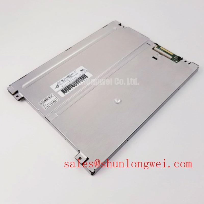
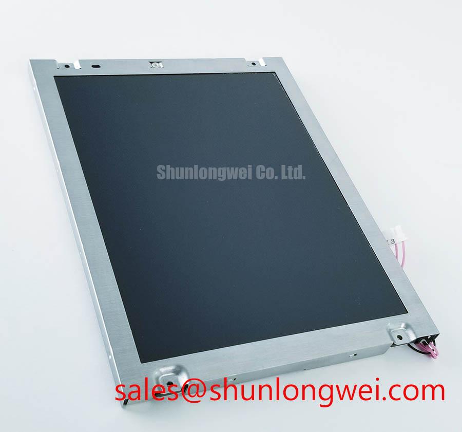
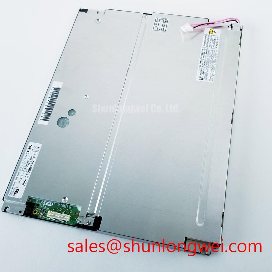
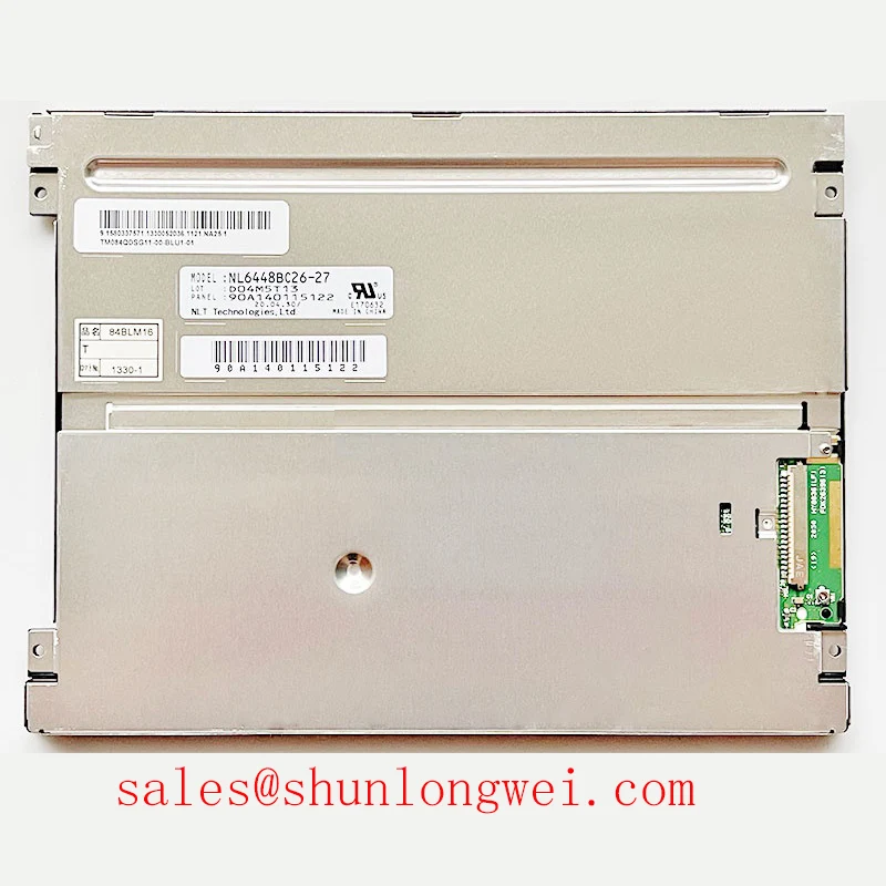
Operating human-machine interface (HMI) displays in railway cab signalling consoles and Passenger Information Systems (PIS) subjects visual electronics to continuous low-frequency mechanical vibration and severe thermal shocks. Within locomotive cab instrumentation, the NEC NL6448BC26-27 operates as a primary visual interface, delivering 640 × 480 (VGA) resolution across an active matrix TFT assembly. When diagnosing field failures characterized by single vertical hairline defects—often appearing as a constant single-pixel-wide line of full red, green, blue, or black—technicians must systematically isolate whether the root cause originates from the digital host controller, the source driver Chip-On-Glass (COG) interconnects, or optical panel fractures.
| Parameter | Specification / Rating | Unit |
|---|---|---|
| Part Number | NL6448BC26-27 | – |
| Manufacturer | NEC | – |
| Display Technology | TFT-LCD Active Matrix | – |
| Resolution | 640 × 480 (VGA) | Pixels |
| Pixel Pitch | 0.267 × 0.267 (Official Datasheet Specification) | mm |
| Display Mode | Normally White, Transmissive | – |
| Operating Temperature Range | -20 to +70 (Extended limits to +80) (Official Datasheet Specification) | °C |
| Storage Temperature Range | -30 to +80 (Official Datasheet Specification) | °C |
| Signal Interface | Digital RGB (6-bit / 18-bit) | – |
| Backlight Life (MTBF) | 50,000 (Typical) (Official Datasheet Specification) | Hours |
Field bench triage begins with a standardized 3-step primary color raster diagnostic. The display unit must be detached from the vehicle logic rack and driven by a calibrated pattern generator supplying solid primary red, solid green, solid blue, pure white, and pure black test frames. In a Normally White transmissive panel such as the NL6448BC26-27, an unpowered or completely disconnected liquid crystal cell defaults to maximum optical transmission. If a single vertical line appears bright white across a solid black test frame, the failure points directly to an open circuit on the source (column) driver line, which deprives that specific sub-pixel column of its switching potential.
To conclusively distinguish between a broken conductive trace within the internal Anisotropic Conductive Film (ACF) bond and a localized scratch on the external optical polarizing film or Light Guide Plate (LGP), maintenance teams apply a 45-degree angled directional light source (flashlight diagnostic) across the de-energized panel surface in a darkened maintenance bay. An external scratch or structural crack in the front polarizing sheet casts a perceptible secondary shadow onto the active LC layer beneath the glass substrate. Conversely, an internal source-driver micro-fracture or ACF delamination exhibits zero surface shadow under oblique lighting while remaining strictly aligned to the 0.267 mm sub-pixel pitch boundary during powered raster sweeps.
When sub-pixel column open circuits occur repeatedly under high mechanical vibration, modernization engineering teams evaluate alternative pin-compatible assemblies or consider upgrading the subsystem to higher-resolution panels such as the NL192108AC21-01 during complete mid-life cab refurbishment programs. Backlight driver modulation must also be evaluated during bench testing; Pulse Width Modulation (PWM) dimming frequencies must be maintained between 200 Hz and 1 kHz (Typical Starting Point for cab backlighting controllers). Running the PWM frequency below 200 Hz produces stroboscopic effects visible under peripheral vision during night transit runs, whereas driving above 1 kHz risks inductive losses and audible ceramic capacitor singing without improving duty-cycle linearity.
Radiated Emissions Compliance (CISPR Class A/B) via Backplate Multi-Point Star Grounding
Railway passenger trainsets and locomotive cabs represent demanding electromagnetic environments. Cab display systems share chassis racks and power conduits with high-power 400V variable frequency motor traction inverters, dynamic braking choppers, and pneumatic compressor relays. Under steep switching transients (high dV/dt), strong radio-frequency common-mode currents couple into unshielded signal harnesses, leading to pixel jitter, horizontal rolling bars, and intermittent loss of display synchronization. Achieving CISPR 11 / CISPR 22 Class A (industrial/railway cab) and Class B limits requires a grounded enclosure strategy centered around the rear chassis of the NL6448BC26-27.
The panel's rear sheet-metal enclosure must serve as a low-impedance ground plane rather than floating at undefined RF potentials. Field engineers must implement 360-degree shielded flat flexible cables (FFC) or shielded twisted pairs carrying the 6-bit digital RGB lines (Clock, Horizontal Sync, Vertical Sync, Data Enable, and 18 data lines). The braided shield of the display cable harness must terminate directly to the chassis ground bulkhead using metal P-clamps with bare metal-to-metal contact, rather than relying on high-inductance pigtail wires. Pigtail connections create parasitic ground inductances that convert common-mode noise into differential noise, generating horizontal scan line distortion when traction inverters ramp up.
Common-mode ferrite chokes with high impedance in the 30 MHz to 300 MHz band must be placed directly at the ingress of the display interface connector. When integrating system topologies alongside adjacent driver architectures such as the NL10276BC16-06, engineers utilize star-point chassis grounding. Multi-point ground screws connecting the LCD perimeter frame to the cast aluminum cab console must maintain continuous ground continuity with an impedance below 0.1 Ω across all contact points.
Maintaining optical legibility under direct sunlight exposure is an operational requirement for locomotive dashboards. The anti-glare (AG) surface treatment on the NEC NL6448BC26-27 disperses specular reflections from cab windows. To ensure critical speed and signal indicators remain readable when ambient illuminance reaches 50,000 lux through forward windscreens, the display assembly must maintain an optical contrast ratio exceeding 500:1. If radiated RF coupling disrupts the common-electrode voltage (VCOM), contrast collapses abruptly, turning dark backgrounds into muddy gray screens and compromising operator visibility during critical operations.
Suppressing Localized Thermal Gradients to Prevent Chronic Optical Yellowing (Color Shift)
Prolonged thermal stress represents a primary failure mechanism in sealed industrial HMI cabinets. In railway passenger information systems, displays often operate 24/7 inside unventilated, IP65-sealed enclosures mounted in ceiling channels or exterior-facing bulkheads. Edge-lit LED backlights concentrate heat generation along the perimeter aluminum rails. If this heat cannot escape, localized thermal gradients develop across the optical stack of the NL6448BC26-27, accelerating the degradation of the polymethyl methacrylate (PMMA) light guide plate.
Under continuous thermal stress exceeding 65°C at the edge rail, PMMA undergoes photo-thermal degradation. This process cleaves polymer chains, generating chromophores that absorb blue wavelengths (400–450 nm). The optical symptom observed in the field is severe chromaticity drift, visible as irregular yellow or brownish banding along the display edge where the LEDs are positioned. To preserve the panel's rated 50,000-hour backlight half-life (L70/B50 metric under Official Datasheet Specifications), thermal pathways must be engineered to conduct thermal energy away from the LED edge directly into the external cast enclosure.
⚠️ Field Alert: During display replacement or maintenance overhauls, technicians must strictly control the torque applied to the perimeter mounting screws. Applying uneven or excessive torque warps the sheet-metal frame, pinching the optical stack against the light guide plate and producing irreversible bright white pressure spots known as mechanical Mura.
- Use an ISO 6789 calibrated torque screwdriver set strictly to 0.35–0.45 N·m (General Industry Design Consideration for M2/M2.5 bezel fasteners).
- Always follow a diagonal cross-tightening pattern, starting from the center-left and center-right out toward the outer corners.
- Ensure that closed-cell ethylene propylene diene monomer (EPDM) or silicone anti-vibration gaskets maintain a steady 25% to 30% nominal compression ratio to seal against track dust while isolating the panel from cabinet flexure.
- Never apply thermal paste directly onto the display's outer plastic layers; use dedicated phase-change thermal interface pads along the designated aluminum spreader brackets.
Detailed explanations of the internal physical dynamics governing liquid crystal orientation, polarizer life, and optical boundary physics are documented in The Ultimate Guide to Industrial TFT LCD Technology. Proper thermal spreading maintains the edge-to-center temperature delta below 8°C across the active viewing surface, preserving color balance across the entire screen during extended operation.
Wide Temperature Operational Margin (-30°C to +85°C) & Sub-Zero Liquid Crystal Viscosity
Rolling stock equipment operating in continental, sub-arctic, or high-altitude routes must boot up reliably following prolonged winter shutdowns without pre-warmed cabins. The NL6448BC26-27 is specified for an operating temperature range of -20°C to +70°C (with extended limits supporting operation up to +80°C) and a storage range of -30°C to +80°C (Official Datasheet Specification). Operating at or below -20°C exposes liquid crystal material to physical limitations that impact dynamic screen updates.
The rotational viscosity of the nematic liquid crystal mixture increases exponentially as temperature drops toward sub-zero levels. At standard room temperature (+25°C), typical Gray-to-Gray (GTG) response times range between 15 ms and 25 ms, allowing smooth rendering of cab velocity dials and alphanumeric signaling texts. When ambient cab temperatures decline to -20°C during an unheated morning cold-start, the increased fluid viscosity can elevate response times to over 150 ms to 300 ms. This leads to noticeable visual ghosting and slow screen refresh, where updated velocity values momentarily overlap previous digits.
To support critical safety consoles operating down to -30°C, external system architectures incorporate thermostatically controlled transparent Indium Tin Oxide (ITO) heater glass placed ahead of the front polarizer, or implement drive-signal overdrive tables within the graphic controller FPGA to speed up sub-zero molecular switching. Thermal cycling between -30°C and +80°C also subjects the perimeter epoxy sealant to significant mechanical stress. The coefficient of thermal expansion (CTE) mismatch between the display's borosilicate thin-film glass substrates and the metallic perimeter frame can induce microscopic gaps in the edge seal if thermal ramps exceed 2°C per minute.
Signal integrity along the 18-bit digital RGB bus requires careful engineering consideration across these thermal extremes. Signal propagation delays through interface lines drift as copper and PCB substrate dielectric constants shift over temperature. Differential lines or digital single-ended buses routed across host controller boards to the display connector must maintain controlled impedance (100 Ω ± 10% for paired interfaces or 50 Ω single-ended TTL/CMOS Digital RGB). System designers must constrain clock-to-data skew to 50 ps or less (General Industry Design Consideration for high-vibration railway digital video lines). Preserving this timing window ensures the receiver latch circuit samples RGB data reliably within the valid data eye, preventing bit dropouts, visual snow, or erratic line shifts throughout demanding railway operating cycles.