


Content last revised on September 10, 2026
Surface Anti-Glare and Anti-Reflective Coating Verification for High Ambient Readability
Inspect the display surface before removing any protective film, adhesive residue, or enclosure gasket. A panel installed behind a damaged window can show reflections, haze, apparent contrast loss, or uneven brightness that originate outside the LCD module itself. Surface condition should therefore be checked alongside the front glass, touch overlay where present, bezel pressure, and the cleanliness of the optical path.
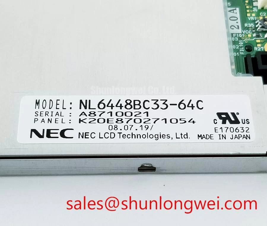
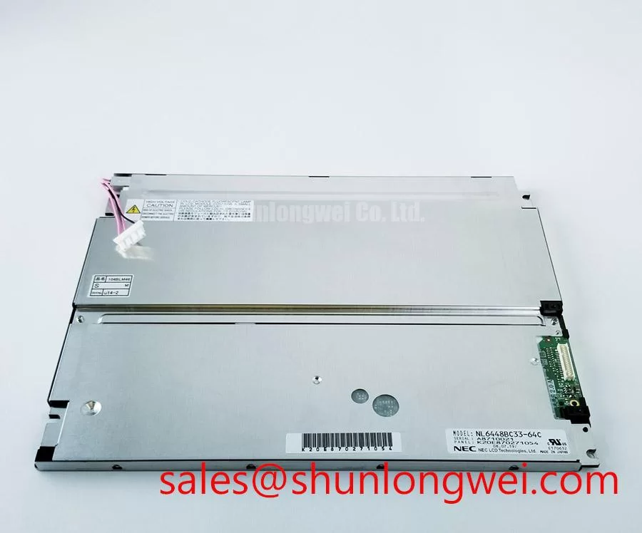
Anti-glare and anti-reflective surface treatments are configuration-specific characteristics. The system integrator should verify the intended surface finish from the original equipment documentation rather than assuming that every unit carrying the NL6448BC33-64C model designation has the same external optical treatment. Under strong ambient lighting, evaluate readability with the panel installed at its intended viewing angle and within the actual enclosure window. A bench observation made with the module lying flat rarely represents the reflection pattern seen at an operator console.
Viewing-angle behavior also requires equipment-level evaluation. TN-type LCD structures can show grayscale inversion when viewed from particular directions, while IPS and MVA technologies are commonly associated with broader symmetric viewing behavior. That general distinction is a Design Consideration, not an official optical specification for this NEC module. Confirm the panel technology, intended viewing direction, and approved mounting orientation from the original display documentation before deciding whether an observed tonal shift is normal for the installed design.
Cold conditions can slow liquid-crystal transitions because viscosity rises as temperature falls. This may be seen as slower changes between gray levels, temporary image trailing, or an interface that appears visually sluggish immediately after start-up. Such observations should not be treated as proof of a defective LCD without first confirming the actual panel temperature, input signal condition, power sequencing, and the equipment’s specified environmental operating range.
Where an enclosure uses a heater strip or controlled warming method, its operation should be verified as part of the host system rather than connected directly to the LCD without an approved design review. Heater placement, control limits, condensation behavior, and local mechanical stress are system-determined. The useful objective is to stabilize the display assembly without introducing uneven heating across the active area or perimeter seal.
For equipment exposed to changing room temperatures, inspect the front gasket for continuous contact around the bezel. A distorted gasket can admit dust or moisture and can also impose uneven loading on the display face. Mounting hardware should hold the module securely while allowing the enclosure design to distribute pressure evenly. Excess local compression can contribute to visible pressure marks or nonuniform areas that resemble optical defects.
Mitigating Gray-to-Gray Response Time Escalation during Cold-Start Machine Power-Up
During a cold-start investigation, begin with the complete power-up sequence rather than judging the panel by the first image displayed. Confirm that the host controller, panel interface, and backlight control path follow the original equipment timing requirements. A white screen, transient image instability, residual image appearance during shutdown, or delayed illumination can arise from several interacting conditions, including sequencing, cabling, controller initialization, and temperature.
The required panel supply voltage and interface type must be verified from the original panel documentation. Do not infer a supply rail, assume an LVDS pinout, or exchange cables based on connector appearance alone. LCD connectors can be physically similar while carrying different signal assignments, logic levels, grounds, or backlight-control functions. For repair work, preserve the original harness routing and record connector orientation before removal.
Flexible printed cables should be handled by their reinforced ends rather than folded close to the termination area. Repeated tight bending, tensile loading during cover removal, or incomplete connector locking can create intermittent image faults that vary with vibration or cabinet temperature. Check that the cable follows its intended service path, that any latch is fully engaged, and that the harness does not pull sideways on the panel connector when the enclosure door closes.
Perimeter seal behavior through thermal cycling is an important Design Consideration. The actual temperature limits and sealing construction of this module must be confirmed from official NEC documentation. In practical maintenance, inspect for mechanical evidence such as bezel distortion, displaced cushioning material, contamination near the edge, or enclosure features that transfer load directly to the glass. These checks are more defensible than assigning a specific cause to a visual symptom without measurement.
LED-backlight operating life, brightness retention, and driver behavior also depend on the complete display assembly. A statement such as a particular brightness-retention duration cannot be assigned to NL6448BC33-64C without an applicable official specification or qualified test source. When brightness is reduced, compare the panel against a known-good assembly under equivalent drive conditions, inspect the enclosure window for discoloration, and verify that the host backlight driver is operating according to its own documented requirements.
⚠️ Maintenance Note: Disconnect power and allow the equipment to reach a safe service state before releasing the display connector or moving the panel harness.
Long-term static HMI screens should be managed by the host application where equipment operation permits. Screen blanking, controlled dimming, and periodic movement of static interface elements are general display-management practices, but their suitability depends on the operational purpose of the machine and must be determined by the system owner. Do not alter a safety-critical display workflow solely to address a suspected image-retention condition.
Full-Screen Primary Color AOI Screening: Stuck Sub-Pixels and Background Uniformity Audit
A controlled visual inspection is more useful than a quick power check. With the display connected through the approved host system, present full-screen red, green, blue, black, and white test images where the equipment service interface permits. Observe the panel from its intended viewing position and note whether an abnormal point, line, shadow, or brightness variation remains fixed across color fields. Record findings before opening the enclosure further.
A fixed point visible on several primary color fields can indicate a pixel-level issue, but diagnosis should remain conditional until the image source and cable path have been checked. A vertical or horizontal line may relate to the panel, connector contact, host output, or mechanical stress near the connection area. Reconnect only after the equipment is safely powered down, then compare the result with a known-good signal path when available.
A dark-area flashlight check at an oblique angle can help distinguish a missing-image condition from a backlight-related condition. If faint image content is visible under controlled inspection while the front appears dark, the observation may point toward the illumination path or its host controls. If the image itself contains stable line defects, the display interface and module should be evaluated together. This is a diagnostic method, not a definitive statement about any internal component structure.
Background uniformity should be assessed after the assembly has stabilized at its normal operating condition. Pressure from an incorrectly seated bezel, trapped debris, warped mounting surfaces, or a compressed gasket can create visible nonuniformity that is absent when the module is removed from the enclosure. Release and reinstall the mounting arrangement only according to the original equipment method, then recheck the same image field.
Backlight dimming behavior must be matched to the original electrical design. PWM frequency, duty-cycle behavior, audible noise, visual flicker, and camera interaction are controlled by the host driver and display architecture. The system integrator should verify the approved dimming method from the original equipment documentation rather than imposing a generic frequency range. If text appears unstable, observe it with a suitable instrument and compare the result against a known-good display path.
When a replacement assessment requires comparison with another industrial display format, the NL10276BC16-06 can be reviewed as a separate panel option. Its mechanical fit, electrical interface, optical characteristics, and firmware compatibility must be independently verified. A similar display category does not establish interchangeability.
Eye-Diagram Voltage Margin and Differential Noise Floor Verification in High-Vibration Bays
For unstable pixels, intermittent horizontal bands, or image jitter near motor-control equipment, inspect the entire signal path before attributing the condition to the display module. Check connector engagement, harness strain relief, grounding continuity, enclosure bonding, and cable proximity to switching conductors. A disturbance that changes when a cable is moved or when nearby equipment changes state may indicate a system-level signal-integrity or electromagnetic coupling issue that requires instrumented verification.
If the original design uses a differential display interface, an eye-diagram assessment can help the system engineer evaluate signal quality at the relevant receiving point. The applicable voltage margin, timing criteria, termination arrangement, and test method are determined by the verified interface standard and host-board documentation. Do not derive these requirements from the LCD module label or from a visually similar panel.
Shield termination strategy should follow the host equipment design. Full cable shielding, connector-shell bonding, and common-mode suppression can be appropriate Design Considerations where conducted or radiated noise is affecting the display path, but the grounding route must be evaluated for the whole cabinet. An added shield connection can change return-current behavior, so any modification should be validated under actual operating conditions rather than treated as a universal correction.
In high-vibration enclosures, route the cable so that the connector is not carrying the mass of the harness. Support points should prevent abrasion and repeated movement while avoiding sharp edges and excessive compression. Inspect the panel mounting features, enclosure frame, and cable retention components for loosening or stress transfer. A display that behaves correctly on the bench but fails after cabinet vibration can require a combined mechanical and electrical assessment.
The linked NL10276BC30-24D is relevant for evaluating related display-module requirements within a broader service review. It should be treated as a separately specified product, with its own documentation checked before any compatibility decision. For enclosure sealing, cable handling, condensation control, and industrial HMI reliability practices, consult Industrial Display & HMI Solutions.