
Replacing an aging Cold Cathode Fluorescent Lamp (CCFL) assembly with an LED backlight strip or LED-illuminated industrial panel is a common field intervention on legacy CNC controllers, PLC HMIs, and medical analyzers. Yet technicians routinely encounter an immediate fault after the swap: the LCD matrix shows faint graphics under a flashlight, while the backlight stays dark, flickers at low brightness, or lights for one second before shutting off. These failures rarely stem from defective LED strips; they occur because CCFL AC resonant inverters and constant-current DC-DC LED drivers obey different load laws, signal polarities, and protection thresholds.
As outlined in our Industrial TFT-LCD LVDS Timing, Backlight Driver Matching, and HMI Field Replacement Engineering hub, successful field replacement requires treating the display data path and the illumination power stage as coupled but distinct subsystems. While the host single-board computer (SBC) supplies the same legacy 4-pin or 6-pin backlight harness—typically carrying Vin, Ground, Enable (ENA/BLON), and Dimming (DIM/PWM)—an LED boost or buck-boost converter interprets those control rails very differently from a Royer-oscillator CCFL inverter.
1. CCFL-to-LED Backlight Conversion: Why Direct Harness Swaps Fail
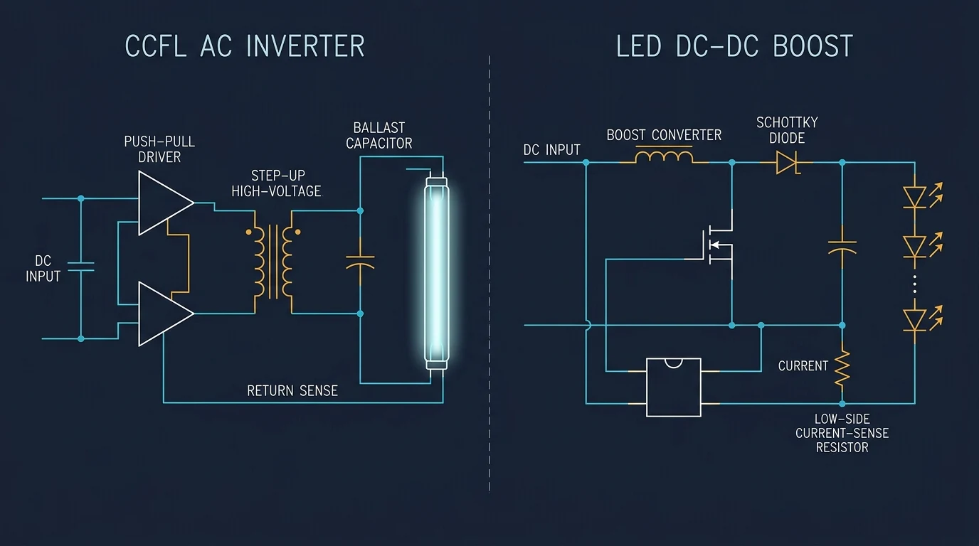
A legacy CCFL tube behaves as a negative-impedance gas-discharge load. Its inverter must generate a high-voltage AC strike output (typically several hundred to well over a thousand volts, depending on lamp length, ambient temperature, and inverter waveform—which is often non-sinusoidal in resonant Royer or piezoelectric stages, so panel-specific RMS and peak strike ratings must be checked in the original datasheet) to ionize the mercury vapor, then regulate down to a lower steady-state AC sustaining voltage through a series ballast capacitor. Because the lamp impedance drops as current rises, CCFL inverters regulate AC RMS current through transformer coupling and resonant tank dynamics.
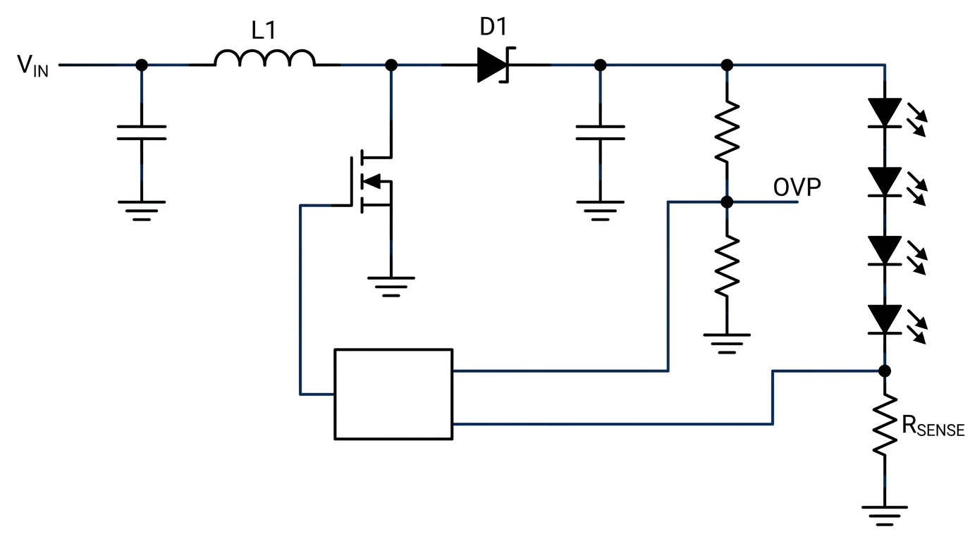
By contrast, an industrial LED backlight rail consists of one or more series-connected strings of forward-biased p-n junction diodes. Once the applied DC voltage exceeds the cumulative forward threshold voltage (N × VF), incremental dynamic resistance becomes very low, meaning small voltage fluctuations produce steep current swings. Consequently, an LED driver must operate as a controlled DC current source—typically using a boost topology when string voltage exceeds the 12 V or 24 V chassis rail—and regulate current across a low-side sense resistor (Rsense).
ILED = VFB / Rsense | Vstring(max) = Nseries × VF(max, cold)
In this first-order design relationship, VFB is the driver IC’s internal current-sense reference voltage (commonly 100 mV to 300 mV in modern integrated boost controllers, though specific thresholds must always be verified in the driver datasheet), and Nseries is the number of LEDs per series string. Notice the cold-temperature term VF(max, cold): silicon/gallium-nitride LEDs exhibit a negative forward-voltage temperature coefficient. At low industrial cold-soak temperatures (for example, -20 °C as an illustrative ambient limit), string forward voltage rises noticeably compared with 25 °C bench measurements, consuming boost headroom and altering overvoltage margins.
2. Enable (ENA/BLON) Logic Levels, PWM Polarity, and Dimming Interfaces
The single most common source of “completely dark screen” and “inverted brightness” faults during a CCFL-to-LED conversion is control-signal incompatibility on the 4-pin or 6-pin backlight header. Legacy CCFL inverter boards from the 1990s and 2000s often accepted 5.0 V TTL enable signals, or relied on open-collector pull-downs, and frequently used DC analog voltage (0 V to 5 V or 0 V to 3.3 V) for brightness control. Modern constant-current LED driver boards, however, exhibit wide variation across manufacturers in both logic thresholds and dimming schemes.
Enable (ENA / BLON) Thresholds and Power-On Sequencing
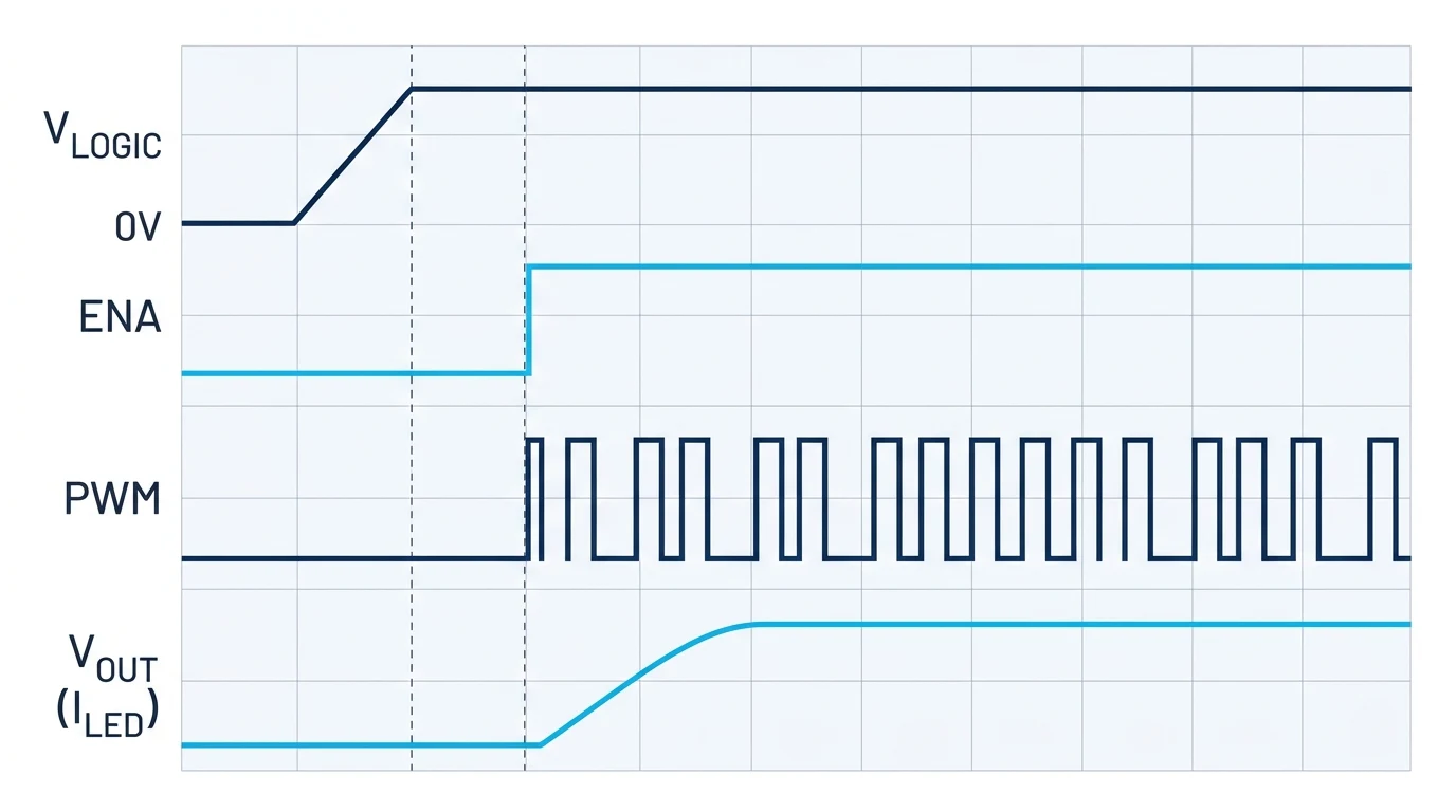
Many legacy host boards drive the backlight enable line through a weak 10 kΩ pull-up to 3.3 V or via a 5 V open-drain buffer, while certain replacement LED driver boards include an internal 4.7 kΩ to 10 kΩ pull-down resistor on the ENA pin to guarantee a safe off-state at power-up. Under a simplified first-order DC divider approximation (neglecting active buffer drive impedance or input clamping diodes), connecting a weakly pulled-up 3.3 V host signal through a 10 kΩ resistor to a 4.7 kΩ–10 kΩ pull-down places the ENA node near 1.06 V to 1.65 V—straddling the undefined logic transition zone of CMOS Schmitt triggers.
- Measure Under Load: Always probe the ENA voltage with the replacement LED driver connected, not open-circuit. Verify whether the driver datasheet specifies a 1.8 V, 3.3 V, or 5.0 V logic-high minimum (VIH) and confirm absolute maximum pin ratings before tying ENA to a 5 V rail.
- Respect Panel Sequencing: Asserting backlight enable before the TFT panel’s logic supply (VCC) and LVDS clock stabilize can produce brief white flashes or gate-driver latch-up stresses. Keep the host controller’s BLON delay intact rather than hard-wiring ENA permanently to Vin.
PWM Dimming Frequency, Polarity Inversion, and Analog vs. Digital Filtering
Brightness control introduces three distinct failure modes when retrofitting an LED driver into an existing HMI chassis:
- Inverted Dimming Polarity: Older industrial inverters often used active-low dimming (0 V = maximum brightness, 5 V = minimum brightness), whereas many modern LED driver ICs use active-high PWM (100% duty cycle = maximum current, 0% = off). Without checking polarity, operators find that turning HMI brightness to “100%” extinguishes the screen entirely.
- Analog-to-PWM Mismatch: If the host SBC outputs a smooth DC analog voltage (e.g., 0.5 V to 4.5 V from a potentiometer or filtered DAC) into a driver expecting a digital PWM square wave, the LED driver will interpret a steady voltage above its logic threshold as 100% duty cycle (locked at full brightness) and a voltage below threshold as 0% (sudden blackout), eliminating intermediate dimming steps.
- Low-Frequency Audible Noise and Strobe Artifacts: When the host generates a low-frequency PWM signal (such as 100 Hz to 250 Hz within the 20 Hz–20 kHz audible band), rapid full-load charge/discharge swings on high-dielectric Class II multi-layer ceramic capacitors (MLCCs) induce inverse-piezoelectric mechanical flexing that couples into the PCB as an audible whine, alongside visible stroboscopic flicker under camera inspection. As discussed in TI Application Note SNVA769 on Backlight Driver Dimming Performance, raising the PWM dimming frequency or selecting a driver IC with internal high-frequency PWM/hybrid dimming—within the driver’s minimum on-time linearity window—mitigates both effects.
3. Constant-Current Boost Headroom, OVP Latch-Off, and Startup Inrush
When a retrofitted LED backlight illuminates for half a second to one second and immediately shuts down, the fault commonly traces back to the driver’s Over-Voltage Protection (OVP) loop or input under-voltage lockout (UVLO) during startup.
How OVP Triggers a 1-Second Blackout
In a boost LED driver, if the LED string opens—either because a solder joint cracked on the replacement strip, a connector pin backed out, or the user installed a 10-LED-series strip whose cumulative cold-start VF exceeds the driver’s boost limit—the current-sense feedback node VFB stays at 0 V. The error amplifier commands maximum duty cycle, driving the boost output capacitor voltage rapidly upward until the resistor divider at the OVP pin crosses its internal clamp threshold. Depending on the controller IC, protection behaves in one of three ways: latch-off (backlight stays dark until input power or ENA is toggled), hiccup mode (periodic brief flash-and-shutdown cycles), or non-latching auto-retry (immediate restart once the transient clears).
VOVP(trip) = VOVP(ref) × (1 + Rtop / Rbottom) > Nseries × VF(max) + Vheadroom
Engineers selecting an aftermarket driver board must verify that the driver’s maximum rated output voltage and OVP trip point sit comfortably above the replacement LED rail’s worst-case forward voltage—including low-temperature VF rise and current-sink headroom—while remaining safely below the output capacitor and Schottky diode voltage ratings. Refer to TI Application Report SLVAEG0 (Some Guidelines and Tips for the LED Driver Application) for the coupled relationship between input voltage, switch current limit, duty cycle, and maximum sustainable string power.
Multi-String Current Imbalance and Input Rail Sag
Larger 10.4-inch to 15-inch industrial panels typically split the LED edge-light bar into two, four, or six parallel strings. Never wire parallel LED strings directly together onto a single-channel constant-current driver without per-string current regulation or matched ballast balancing. Due to manufacturing VF binning tolerances and asymmetric thermal gradients along the aluminum frame, the slightly warmer or lower-VF string hogs disproportionate current, accelerating localized phosphor degradation and eventually opening that string—which then dumps excessive current into the remaining strings and causes cascading failure.
Multi-channel drivers such as those patterned after the TI TPS61196 6-string WLED driver architecture employ dedicated low-side current sinks per channel with adaptive boost voltage control, regulating the boost rail just high enough to satisfy the highest-VF string. Additionally, verify the host chassis 12 V or 24 V rail impedance: a tired electrolytic capacitor on an older machine power supply can droop below the LED driver’s UVLO threshold during the boost inductor’s initial charging surge, mimicking a dead backlight.
4. Industrial LCD Backlight Replacement: Optical Uniformity, Thermal Coupling, and Panel Swaps
Even when electrical matching is flawless, a field technician must evaluate whether retrofitting an LED strip inside an existing CCFL chassis is mechanically and optically viable. Before opening the lamp cavity, isolate chassis power and allow inverter high-voltage capacitors to discharge; handle spent CCFL glass tubes carefully to prevent breakage and mercury exposure. CCFL-era panels rely on acrylic (PMMA) light-guide plates (LGPs) and multi-layer optical diffuser/prism films engineered for the 360-degree cylindrical emission profile of a fluorescent tube. Over years of 24/7 operation, sustained thermal stress near the CCFL electrodes, polymer aging, and ambient contaminants (heat, humidity, and airborne dust) cause yellowing and micro-crazing along the PMMA injection edge. Inserting a directional LED bar into a degraded LGP yields uneven brightness, dark corners, or visible bright “hotspots” along the injection edge.
Thermal coupling requires equal discipline. An LED strip dissipates concentrated heat along its aluminum-core PCB (MCPCB). If the strip is merely held in place with foam tape inside a plastic lamp reflector—rather than bonded with thermally conductive adhesive or mechanical clips directly to the panel’s metal rear chassis—junction temperatures climb rapidly, accelerating lumen depreciation and color shift. Adequate thermal conduction into the metal frame and chassis airflow remain mandatory; LED retrofits reduce localized inverter transformer heat, not the fundamental need for a defined thermal path.
When an existing CCFL display exhibits yellowed polarizers, LGP discoloration, or failing TAB/COF gate bonds alongside lamp failure, replacing the entire display module with an industrial-grade replacement panel is typically more reliable than rebuilding the lamp cavity. For example, in 8.4-inch SVGA industrial HMIs, engineers frequently evaluate a drop-in industrial panel such as the Mitsubishi AA084SA01 8.4-inch 800×600 industrial TFT-LCD, verifying mechanical mounting tabs, bezel gasket clearance, and backlight connector matching against the original enclosure. Similarly, for 10.4-inch open-frame machine-tool interfaces undergoing full display refurbishment, a dedicated industrial module like the Mitsubishi AA104VH12 10.4-inch industrial TFT-LCD provides traceable factory origin and consistent lot-to-lot optical alignment when paired with a verified backlight driver and interface harness.
Pre-Installation Compatibility Checklist
- Input Rail: Confirm 12 V / 24 V supply matches driver Vin and sustains startup surge without UVLO droop.
- String Limits: Verify Nseries × VF(max, cold) sits below VOVP(trip) and Rsense matches rated ILED.
- Control Logic: Check ENA VIH under load, PWM vs. analog DC mode, and active polarity.
- Connector Pinout: Verify power, GND, ENA, and DIM pin positions against the host harness before power-on.
- Mechanical Fit: Confirm LED strip length, thickness, and reflector clearance fit the lamp cavity without pinching.
- Thermal Path: Thermally bond the LED MCPCB directly to the metal rear frame.
5. Field Diagnostic Matrix for CCFL-to-LED Retrofits
Before condemning a newly installed LED driver board or replacement LCD module, isolate the fault systematically using the diagnostic matrix below. Always probe signals with an oscilloscope and bench multimeter referenced to the driver’s power ground.
| Observed Symptom | Primary Electrical Root Cause | Oscilloscope / Multimeter Verification | Corrective Engineering Action |
|---|---|---|---|
| Backlight stays completely dark; faint image visible | Missing or attenuated ENA/BLON logic level; swapped power polarity; driver held in UVLO | Measure ENA pin voltage under load relative to GND; verify Vin during power-on | Match ENA pull-up/pull-down impedance; verify 3.3 V vs. 5.0 V logic threshold per driver datasheet |
| Lights up for ~0.5–1.0 s, then shuts off | OVP trip from open LED string, reversed strip polarity, or boost Vout exceeding OVP divider | Capture Vout peak on oscilloscope during startup; check LED strip continuity and VF | Reseat LED harness; verify string Nseries × VF sits below driver VOVP(trip) |
| Brightness works backward (100% setting = dim/off) | PWM dimming polarity mismatch (active-low host vs. active-high driver) | Measure PWM duty cycle vs. optical brightness at 10% and 90% HMI settings | Add a single NPN/NMOS logic inverter stage or reconfigure driver polarity strap if supported |
| No intermediate dimming; snaps full on or off | Analog DC dimming voltage fed into digital PWM input pin | Inspect DIM pin on oscilloscope: flat DC voltage instead of square-wave pulses | Use a driver supporting analog DC dimming, or convert 0–5 V DC via a PWM generator interface |
| Audible whine or visible flicker at low brightness | Low host PWM frequency (<300 Hz) causing MLCC piezoelectric noise or beat-frequency strobe | Measure PWM frequency on DIM pin; listen near boost output ceramic capacitors | Increase PWM frequency per driver spec, or select a driver with high-frequency hybrid dimming |
| Uneven edge brightness or rapid dimming over weeks | Single-channel driver feeding unmatched parallel LED strings, or unbonded MCPCB overheating | Compare individual string currents; check rear chassis temperature near lamp edge | Switch to multi-channel balanced current-sink driver; bond MCPCB thermally to metal frame |
6. Engineering FAQs: CCFL-to-LED Backlight Replacement
Can an LED strip replace a CCFL tube directly without changing the driver?
No. CCFL tubes require high-voltage AC resonant inverters, whereas LED strips require regulated DC constant-current drivers.
Can the original CCFL inverter board drive an LED backlight?
No. CCFL inverters output high-voltage AC via transformer coupling and ballast capacitance; they lack DC constant-current regulation and low-voltage OVP feedback.
Why does a retrofitted LED backlight turn on for one second and shut off?
A 0.5–1.0 s flash followed by shutdown typically indicates an OVP trip (open string, reversed polarity, or cold-start Vstring exceeding boost limits) or input UVLO sag.
Should I replace only the LED strip or the entire TFT-LCD module?
If the PMMA light-guide plate is yellowed, polarizers are blistered, or TAB/COF bonds are failing, full TFT-LCD module replacement is more reliable.
By verifying ENA impedance, dimming polarity, boost OVP headroom, and thermal mounting before closing the HMI chassis, technicians can prevent the most common retrofit failures. For LVDS timing, bit-mapping, and full panel replacement procedures, see our main hub: Industrial TFT-LCD LVDS Timing, Backlight Driver Matching, and HMI Field Replacement Engineering.