

Content last revised on September 14, 2026
Incoming Benchtop Inspection: COG/TAB Anisotropic Conductive Film Integrity
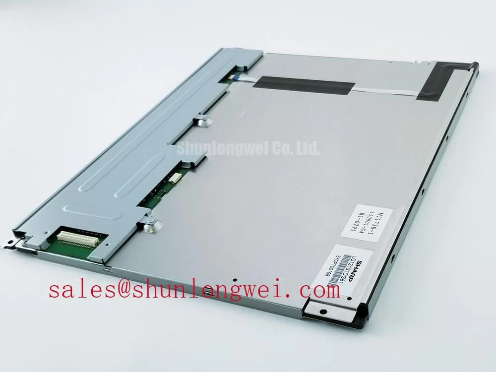
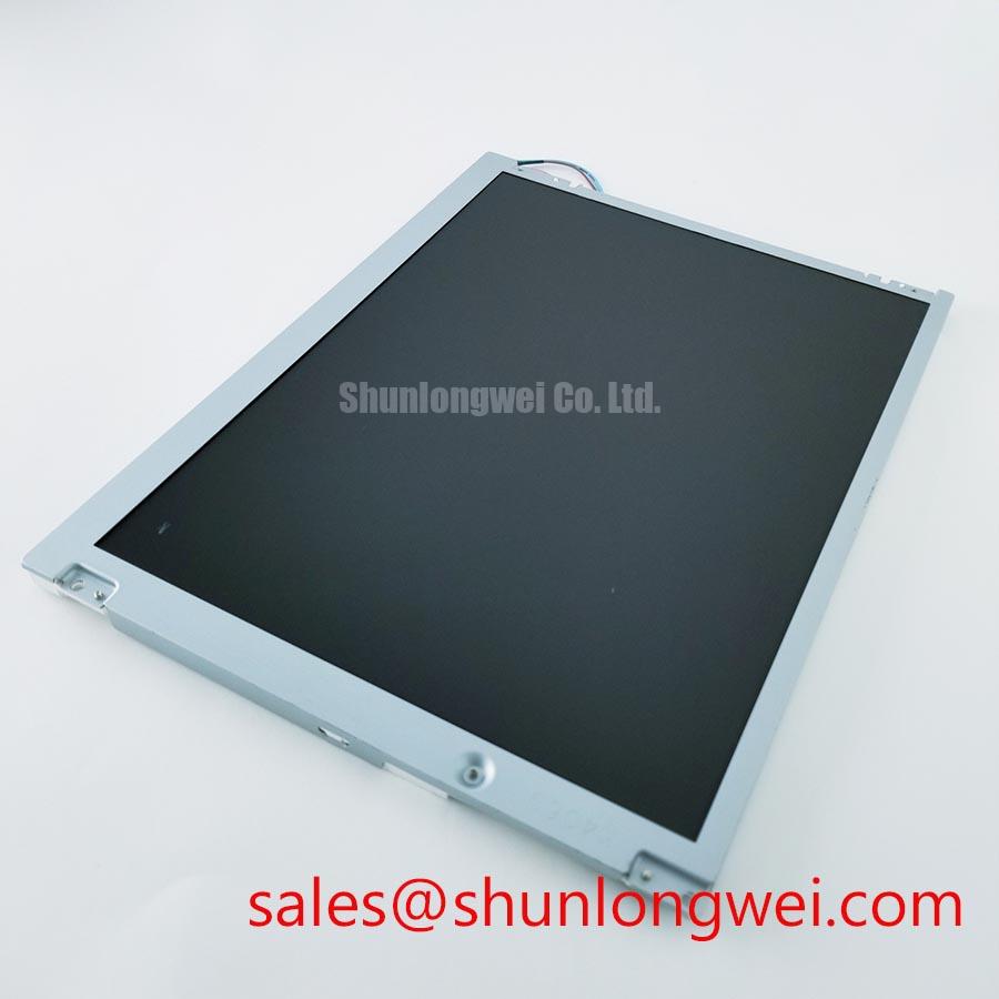
Disconnect the display from the host equipment, record the identification label, and inspect the Sharp LQ121S1DG42 before applying power. Check the TFT-LCD Display Module for cracked glass, bezel distortion, damaged flex areas, contamination around the connector, and signs of uneven mechanical loading. These checks establish whether a dark image is more likely to involve the panel assembly, the backlight circuit, the signal path, or the host system.
The documented product category for this model is Industrial Grade LCD/HMI Panel, with a TFT-LCD Display Module construction designation and an Official Factory Spec Verified status in the supplied product data. The available factory information does not confirm the display resolution, active area, supply voltage, interface type, backlight electrical ratings, brightness, viewing angle, touch function, or operating temperature range. The system integrator should verify each of these items against the original panel documentation before installation.
For a basic incoming test, connect the panel only to a known-good controller and the correct approved power and signal harness for the original equipment. Do not assume that a similar connector has the same pin assignment. Confirm the connector keying, cable orientation, enable signals, and power sequencing from the equipment documentation. If the panel remains dark, use a controlled primary-color test pattern where the host system supports it. Red, green, blue, white, and black fields can help reveal whether the image data reaches the panel evenly.
A flashlight test at approximately a 45-degree angle can help separate a backlight problem from an image-generation problem. A faint image visible through the front surface may indicate that the liquid crystal image is being driven while the illumination path requires further testing. An entirely uniform black field does not establish a single fault source, so the controller output, panel supply, enable timing, and connector continuity should be checked together.
COG and TAB areas require non-invasive inspection. Do not press the glass edge, flex region, or bonded driver area while the display is operating. Temporary changes caused by pressure can conceal an intermittent connection and can create additional damage. A controlled temperature change may expose an intermittent fault during service testing, but the result should be compared with a known-good signal path rather than treated as proof of a particular internal defect.
In high-EMI factory environments, differential display wiring should be routed away from switching nodes, contactors, servo drives, and unfiltered motor cables. Maintaining a consistent differential pair geometry and minimizing unnecessary cable length are general Design Considerations. If the original system documentation specifies approximately 100 Ω differential impedance or a particular skew limit, the installed cable and connector arrangement should be checked against that requirement. Those values should not be treated as confirmed electrical specifications of the LQ121S1DG42 itself.
Field Alert: Remove power and allow the equipment discharge procedure to finish before disconnecting or inserting the display cable, because live signal or supply contacts can be exposed to electrical stress during insertion.
| Item | Confirmed information |
| Model | Sharp LQ121S1DG42 |
| Product category | Industrial Grade LCD/HMI Panel |
| Module designation | TFT-LCD Display Module |
| Specification status | Official Factory Spec Verified |
| Unconfirmed items | Resolution, interface, voltage, current, brightness, touch function, temperature rating, and backlight details require documentation verification |
Thermal Expansion Clearance Sizing across Heavy Industrial Metal Enclosure Cutouts
Before fitting the panel into a heavy metal enclosure, compare the original cutout drawing with the replacement module outline. The bezel must sit evenly against the mounting surface without twisting the glass or forcing one corner into contact with the chassis. Check for burrs, paint buildup, welded distortion, and cable pinch points. A rigid enclosure can transfer vibration and thermal movement directly into the display frame when the cutout or fastener pattern is not aligned.
Fastener loading is a system-level installation matter. If the equipment drawing specifies M3 hardware, use the documented torque for that enclosure and mounting arrangement. A cross-pattern tightening sequence is a useful Design Consideration because it distributes mechanical loading more evenly than tightening one corner fully before the others. The supplied information does not identify an official mounting torque for this model, so values such as 0.35 to 0.45 N·m must not be presented as a Sharp factory requirement.
Thermal clearance should be evaluated at the complete assembly level. The panel, bezel, gasket, metal cutout, cable, and mounting hardware may expand differently during operation. Designers should provide clearance according to the enclosure material, expected temperature range, vibration profile, and sealing method, then confirm that the glass remains free from localized pressure during thermal cycling. Optical non-uniformity, corner darkening, or a changing shadow can have several possible causes, including illumination aging, mechanical stress, connector conditions, or controller behavior.
Backlight lifetime claims require particular care. A commonly cited industry figure such as 50,000 hours to 50 percent brightness is not an official specification for the LQ121S1DG42 in the supplied data. It should not be used in a maintenance forecast unless it appears in the applicable Sharp documentation and is tied to defined current, temperature, duty cycle, and measurement conditions. For service planning, record actual luminance trends from representative equipment and identify the test method and operating conditions.
When the display is installed behind a protective window, check the optical stack rather than assuming the module itself provides a specific anti-glare or anti-reflective treatment. Ambient reflections are affected by the window surface, air gap, coating, bezel depth, lighting position, and display surface. The original panel documentation should confirm whether the LQ121S1DG42 includes an AG or AR surface treatment. If that information is unavailable, evaluate the replacement in the completed enclosure under the actual operator lighting.
For a potential Zone 2 petrochemical operator station or field monitoring terminal, the LCD panel should be evaluated as one part of the certified enclosure assembly. The display module does not independently establish explosion protection, ingress protection, temperature classification, EMC compliance, or hazardous-area certification. The equipment designer must verify the complete station design, barrier arrangements, cable entries, window construction, thermal behavior, and applicable certification requirements.
Where a same-size or similar-resolution replacement is being considered, compare mechanical drawings and interface documentation rather than relying on nominal diagonal size alone. The LMS700KF01-001 may be reviewed as a separate display option, but compatibility remains dependent on connector assignment, timing, mounting geometry, optical behavior, and system voltage requirements.
Preventing Frame Lag and Image Smearing in Cryogenic Storage and Outdoor Industrial Facilities
When a display appears slow after exposure to cold conditions, first document the panel temperature, controller behavior, refresh pattern, and transition being observed. Liquid crystal response can vary with temperature, but the exact response behavior of this model cannot be confirmed from the supplied factory data. A slow gray transition, a delayed complete frame, and a backlight control problem can look similar to an operator, so each should be checked separately.
Use moving test patterns and alternating gray fields while monitoring the controller output and panel supply. Compare the result at the normal service temperature and at the lowest temperature permitted by the original equipment documentation. If the image data remains stable but the visual transition changes, the panel temperature response may require review. If the data waveform, enable timing, or supply rail changes, the system electronics must be investigated before assigning the issue to the liquid crystal layer.
The LQ121S1DG42 documentation supplied for this page does not confirm a specific industrial temperature range, epoxy sealant specification, LVDS assignment, TTL compatibility, clock rate, jitter margin, or data hold time. Designers should verify these parameters from the original Sharp documentation and the host controller design. A display connector that physically mates with the system is not sufficient evidence of electrical compatibility.
For outdoor equipment, protect the module from condensation, direct water exposure, ultraviolet exposure, and rapid temperature changes through the enclosure design. Any gasket or perimeter sealing method must be selected for the complete product, including the window, bezel, cable entry, and service access. The LCD module should not be described as independently weatherproof or suitable for a stated temperature class without a supporting manufacturer specification.
Signal integrity testing should compare the replacement panel with a known-good unit using the same controller and cable route. Probe placement matters because a long oscilloscope ground lead can add misleading ringing to a fast display signal. Designers should minimize coupling from high-current switching circuits, maintain the original pair routing where practical, and verify waveform quality at the panel connector under operating load. The final acceptance limits are determined by the controller and panel interface documentation.
Touch operation requires separate verification. The supplied data identifies the product as an LCD/HMI panel but does not confirm a resistive touch layer, capacitive touch layer, glove sensitivity, wet-finger performance, or touch controller interface. If the replacement is intended for an operator station, confirm the original touch technology, overlay construction, calibration method, and protective window arrangement. A bright and stable image does not prove that touch input will function correctly with gloves or moisture.
For engineering qualification, test the complete display assembly rather than the loose module alone. Observe startup, shutdown, repeated image changes, cable movement, enclosure vibration, and temperature transitions while recording the actual panel behavior. Any acceptance decision should be based on the original equipment requirements and documented test conditions, not on an assumed generic LCD performance profile.
Super IPS or MVA Wide Symmetric Viewing Cone for Multi-Angle Consoles
Multi-angle operator consoles should be checked from the real standing and seated positions used in the equipment. Observe black, white, and mid-gray images from the left, right, top, and bottom while changing the ambient light direction. This practical inspection can reveal contrast loss, grayscale inversion, glare, or uneven illumination that is not visible during a straight-on bench test.
The supplied factory information does not identify the LQ121S1DG42 panel mode as TN, IPS, Super IPS, or MVA. It also does not confirm a symmetric viewing specification such as 85° in four directions. Those values must not be assigned to this model without the applicable Sharp datasheet. A replacement decision should use the documented viewing-angle definition and contrast criterion, because viewing angle can be reported using different measurement methods.
TN, IPS, and MVA technologies can produce different off-axis grayscale and contrast behavior, but general technology descriptions do not replace model-specific measurements. If operators report a washed image or reversed gray steps, reproduce the condition with controlled test patterns and compare the viewing position, ambient illumination, surface reflections, and controller settings. This approach avoids treating one visual symptom as proof of a particular panel technology or internal defect.
AG and AR performance must also be assessed at the assembly level. An anti-glare surface can reduce mirror-like reflections, while an anti-reflective treatment can reduce some surface reflection through optical design. The result depends on the panel surface, cover window, bonding or air gap, cleaning condition, and surrounding light sources. Since the supplied data does not confirm the LQ121S1DG42 surface treatment, the integrator should verify the original documentation and perform a direct comparison in the target console.
LED backlight aging should be handled as a documented maintenance topic, not an assumed product guarantee. The supplied data provides no official luminance lifetime curve or defined brightness retention point for this model. If the equipment owner needs a replacement interval, establish it from measured luminance, operating temperature, drive conditions, duty cycle, and the minimum readable level required by the application. Any lifetime figure used in procurement documentation should identify its manufacturer source and test conditions.
For high ambient light installations, evaluate the complete optical path with the enclosure door closed and the actual operator lighting active. Confirm that the display remains readable through the protective window and that the chosen surface treatment does not introduce excessive haze or reduce critical detail. In a petrochemical monitoring terminal, the panel remains one component within a larger certified HMI assembly. The enclosure designer must verify hazardous-area compliance, EMC behavior, touch performance, and environmental protection for the finished system.
Additional application guidance is available in the Industrial Display & HMI Solutions engineering resource. For procurement and service replacement, the key control point is documentation matching: confirm the electrical interface, mechanical envelope, optical requirements, operating limits, and host-system timing before releasing the Sharp LQ121S1DG42 for installation.