Content last revised on September 10, 2026
NEC NL12876BC26-25A LCD Display: Field Verification Before Installation
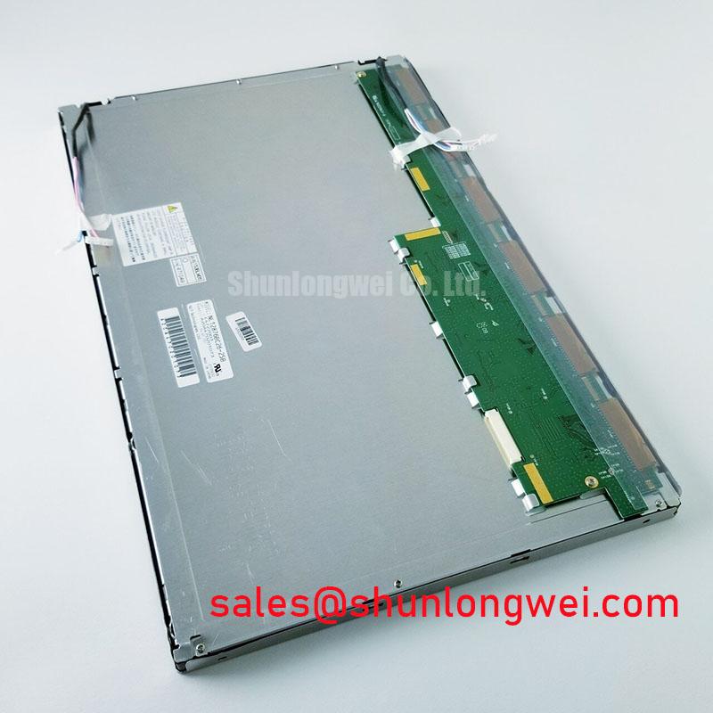
Before fitting NL12876BC26-25A into a replacement control panel, inspect the TFT-LCD module for connector damage, frame distortion, surface marks, and label consistency, then compare the host equipment documentation with the required electrical and mechanical interfaces.
NL12876BC26-25A is identified in the available factory specification context as an NEC Industrial Grade LCD/HMI Panel. Its package or external assembly classification is a TFT-LCD Display Module, and the specification status is listed as Official Factory Spec Verified. The information supplied for this product does not establish a complete pinout, resolution, active-area size, supply voltage, backlight electrical rating, touch technology, or operating-temperature rating. Those values should be confirmed against the original NEC documentation and the equipment manufacturer’s service records before connection.
| Parameter | Available product information | Engineering use |
|---|---|---|
| Model | NL12876BC26-25A | Use the complete suffix when checking replacement compatibility |
| Manufacturer | NEC | Confirm the original panel identification and host equipment record |
| Product category | Industrial Grade LCD/HMI Panel | Suitable for technical evaluation in industrial display assemblies |
| Package or enclosure | TFT-LCD Display Module | Check mounting points, bezel clearance, cable exit, and optical opening |
| Specification status | Official Factory Spec Verified | Use the applicable factory document for final electrical approval |
For repair purchasing, the model suffix matters because a visually similar LCD can still differ in interface mapping, backlight drive requirements, cable orientation, or mounting geometry. A replacement review should therefore compare the complete part marking, connector position, display opening, control-board clearance, and optical stack rather than relying only on diagonal size or external appearance.
Digital RGB Bus Synchronization and Logic Power Rail Verification
If the host controller uses a TTL digital RGB interface, the integrator should confirm that the signal count, pixel clock arrangement, color depth, synchronization polarity, and data order match the original panel documentation. The available product information does not independently confirm that this specific module uses a TTL 24-bit bus, so the interface must not be assumed from the model number alone.
During a bench replacement test, compare the known-good display path with the candidate module using the original controller, cable assembly, and power sequence wherever practical. Check whether the host presents separate red, green, and blue data groups, horizontal and vertical synchronization, data enable, and a pixel clock. A split image, incorrect colors, unstable synchronization, or intermittent picture can arise from several conditions, including data mapping differences, clock polarity, cable contact quality, or an unsuitable logic rail. Oscilloscope comparison against the known-good signal path is more reliable than assigning one symptom to one cause.
The system integrator should verify the required supply voltage from the original panel documentation. Do not select between common logic-rail values based on appearance or connector similarity. The same caution applies to power-on timing. The host controller, panel logic, backlight circuit, and any touch controller may have separate enable and reset requirements. Designers should confirm the required rise-time and sequencing limits from the applicable factory documents, then validate the complete startup waveform at the panel connector.
Where the host interface requires controlled differential routing, a 100 Ω differential characteristic impedance is a Design Consideration for the interconnect rather than an asserted factory parameter of this LCD module. The PCB designer should control pair geometry, reference-plane continuity, return-current paths, and connector transitions according to the controller and cable specifications. JEIDA or VESA color mapping should also be verified from the original panel records. Incorrect mapping can produce a stable-looking image with swapped color significance or abnormal grayscale transitions.
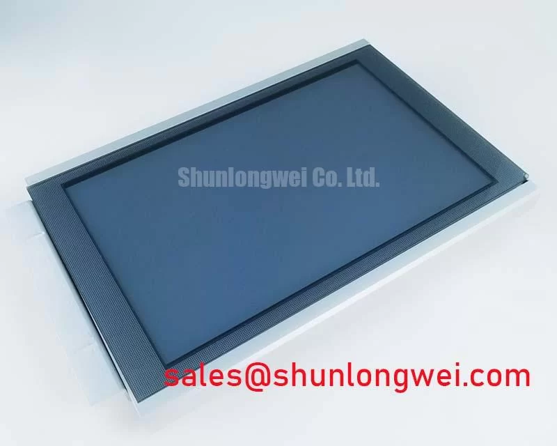
Outdoor or high-illumination machine areas require an optical inspection under the actual enclosure lighting. Measure readability with the cover, window, and any protective film installed. Ambient reflections, viewing angle, surface contamination, and the condition of the anti-glare or anti-reflective treatment can influence practical contrast. A contrast value or sunlight performance level should not be assigned to NL12876BC26-25A without the applicable factory optical specification. If the module is being considered for a CNC operator panel or robot teach pendant, verify the complete optical stack and front-window geometry before approving the repair.
💡 Pro Tip: Keep the pixel-clock and associated signal paths physically consistent, then verify clock quality and image stability at the panel connector after the final cable and chassis are installed.
Industrial EMI Noise Immunity, Chassis Shielding Continuity, and Common-Mode Filtering
Industrial control cabinets frequently place display wiring near switching supplies, servo amplifiers, variable-frequency drives, contactors, and motor cables. This does not establish a specific EMC rating for the NEC module, and a display module must not be represented as independently certified for complete-machine emissions or immunity. The correct task is to evaluate the installed assembly, including the controller, cable, chassis, bonding, and enclosure.
Start by checking the cable route and connector seating with power removed. A loose shield termination, incomplete chassis bond, damaged flex tail, or poorly supported cable can create intermittent pixel errors that resemble a timing fault. For an LVDS-based host, confirm the actual interface before applying differential-pair assumptions; for a TTL host, inspect the single-ended signal reference and return path. The original cable pinout and shielding construction should remain the primary reference.
For a differential link, controlled impedance is a Design Consideration. A 100 Ω target with an appropriate tolerance may be used when required by the host transceiver and interconnect specification, but the final value depends on the controller, cable, connector, and board stack-up. Pair-to-pair skew should likewise be evaluated against the receiver’s timing budget instead of being assigned a universal limit to this product. Verify eye quality, clock stability, and data transitions under the actual cabinet noise conditions.
A common-mode ferrite choke can be considered when conducted or radiated noise is observed on a compatible differential cable, but its impedance profile, current capability, placement, and effect on signal integrity must be checked by the system designer. It is not automatically suitable for every display bus. Testing should compare the display with the motor drive operating and stopped, while monitoring the supply rail and interface waveform. Horizontal noise bands, pixel jitter, or temporary loss of synchronization may require investigation of grounding, power conversion, cable coupling, or controller timing together.
Maintain a continuous, low-impedance chassis shield path around the display cable where the mechanical design supports it. The effectiveness of a shield depends on termination geometry and enclosure bonding, not simply on attaching a drain wire at one end. For a CNC operator panel or robot teach pendant, review the cable exit, hinge movement, strain relief, and conductive enclosure surfaces as one assembly. Link-level improvements should be validated after the display is installed behind its final front panel.
Cross-reference work may include the NL8048AC19-13KD when engineers are reviewing another industrial display option. This is a neutral comparison path, not a substitute recommendation; physical, electrical, optical, and firmware compatibility still require confirmation.
Thermal Cycling, Polarizer Surface Condition, and Perimeter Seal Inspection
The supplied factory parameter set does not provide a confirmed operating-temperature range, thermal-cycle qualification, liquid-crystal response specification, polarizer construction, or perimeter sealant rating for NL12876BC26-25A. Engineers should therefore treat any cold-start or elevated-temperature evaluation as a system validation activity rather than as proof of a product guarantee.
For equipment exposed to rapid temperature changes, inspect the front polarizer, edge seal region, flex connections, and mounting frame after conditioning. Look for lifting, bubbles, edge separation, haze, or mechanical interference, while recognizing that the cause may involve enclosure stress, condensation, cleaning chemicals, frame distortion, or thermal expansion elsewhere in the assembly. The display should be checked in its installed orientation with the actual bezel and window, since restraint at the edges can alter mechanical loading.
At sub-zero temperatures, liquid-crystal response can become slower as a general display technology consideration. If a machine must start in a cold environment, measure gray-to-gray behavior, refresh stability, startup time, and image uniformity at the temperatures defined by the equipment specification. A heater strip may be considered only after the thermal path, power budget, local hot spots, and control method have been reviewed. Its use should not be assumed for this NEC module without supporting documentation.
At elevated temperature, examine brightness uniformity, image retention, polarizer appearance, and backlight behavior during a controlled test. The display assembly, driver electronics, and enclosure ventilation should be assessed together. Avoid placing heat-producing components directly against the rear of the module, and provide mechanical support that limits vibration without loading the active area or flexible connections.
The linked NL128102BC28-04 can be reviewed as a related display-system reference when assessing upstream power or auxiliary display architecture. It should not be treated as an established companion device for this model unless the original equipment documentation confirms that relationship.
Diffuser Film, Prism Sheet, and Continuous Full-Duty Display Integration
The available information identifies this product as a TFT-LCD Display Module but does not confirm its backlight technology, optical film construction, LED arrangement, diffuser material, prism-sheet design, L70 or B50 performance, or backlight protection circuit. Integrators should verify these details from the applicable panel documentation before designing a replacement backlight supply or modifying the front housing.
When the original assembly uses an LED backlight, the backlight driver should be checked separately from the LCD signal path. Confirm the required enable behavior, dimming method, current regulation, open-load response, short-circuit response, and overvoltage behavior from the driver and panel documents. A dark screen can involve the backlight, logic supply, timing controller, cable, or image source, so diagnostic work should first determine whether image data is present before changing the illumination circuit.
Continuous full-duty operation calls for a mechanical and thermal review of the complete display bay. Aluminum heat-spreader rails may be considered along suitable frame regions when they improve heat distribution without obstructing the optical path or applying stress to the module. Rail dimensions, contact pressure, insulation, and attachment method are system-design decisions that require thermal measurement in the final enclosure. Do not infer a guaranteed backlight life or optical-film lifetime without a published factory rating.
Inspect the diffuser and front optical surfaces for contamination, pressure marks, warping, and localized discoloration during service. Uneven illumination can also result from driver-current imbalance, connector resistance, enclosure reflection, or mechanical compression. Compare the repaired assembly with a known-good reference under identical brightness and camera exposure conditions, then confirm operator readability through the actual protective window.
For a CNC operator panel or robot teach pendant, the final compatibility review should include the mounting aperture, bezel overlap, cable bend space, control-board clearance, touch function if present, and the host firmware’s display timing. If the original system includes a resistive or capacitive touch layer, verify that layer as a separate interface; the product category alone does not confirm touch capability or glove and moisture performance. Practical installation and environmental test criteria can be reviewed alongside Industrial Display & HMI Solutions.
🔧 Bench Diagnostic: Disconnect power before inserting or removing the display cable, and verify connector orientation and pin assignment against the original equipment documentation.