In the realm of industrial automation and power electronics, the Variable Frequency Drive (VFD) is the workhorse of modern motion control. However, a silent conflict exists within every drive system: the tension between inverter efficiency and motor lifespan.
As engineers push for faster switching speeds to minimize thermal losses, the resulting high voltage rise rates (dv/dt) create hazardous conditions for the motor’s insulation system. This article analyzes the failure mechanisms associated with Pulse Width Modulation (PWM) control, explores the “controllability” breakthrough in modern semiconductors (specifically 7th-generation IGBTs), and provides design strategies to limit dv/dt without sacrificing system efficiency.
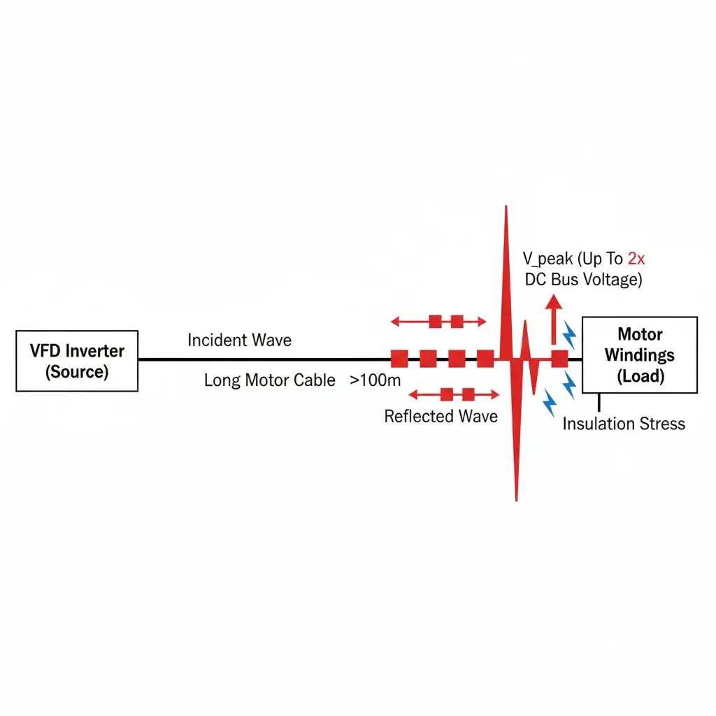 Figure 1: Illustration of the Reflected Wave Phenomenon in long-cable motor drive applications.
The Physics of Failure: How PWM Affects Motor Insulation
To understand why controllability is critical, we must first analyze the destructive nature of uncontrolled dv/dt. Modern VFDs use PWM to synthesize a sine wave current. While effective, this technique generates high-frequency voltage pulses with steep edges.
1. The Reflected Wave Phenomenon
When these fast-rising pulses travel through a long motor cable, the cable acts as a transmission line. Due to the impedance mismatch between the cable and the motor windings, the voltage pulses are reflected back toward the drive.
The physics of this mismatch is defined by the Reflection Coefficient (Γ):
=
Where Zmotor is the motor’s surge impedance and Zcable is the cable’s characteristic impedance. Since Zmotor is typically much higher than Zcable, the coefficient Γ approaches 1, causing the reflected voltage to nearly double the incident voltage.
When the forward and reflected waves superimpose, the voltage at the motor terminals can double (or even triple) the DC bus voltage.
For a standard 400V system, the DC bus is approximately 560V. With reflection, the motor terminals may see spikes exceeding 1,200V to 1,500V, a stress level explicitly categorized in the NEMA MG 1 Part 31 standard for inverter-duty motors.
2. Partial Discharge and Insulation Aging
These voltage overshoots stress the inter-turn insulation of the stator windings. If the voltage exceeds the Corona Inception Voltage (CIV) of the insulation, Partial Discharge (PD) occurs. This phenomenon creates microscopic arcs within air voids in the insulation, generating ozone and heat that chemically degrade the enamel. Over time, this leads to:
- Short circuits between turns (inter-turn faults).
- Ground faults.
- Catastrophic motor failure.
Furthermore, high dv/dt induces common-mode currents that couple capacitively to the rotor, causing bearing currents (see ABB Technical Guide No. 5) that result in fluting and premature bearing failure. For a deeper analysis of these phenomena, Yaskawa’s technical analysis on motor bearing currents also provides excellent insights.
The Engineering Dilemma: Efficiency vs. Protection
Traditionally, engineers faced a “hard” trade-off when selecting IGBT Modules and designing gate drivers:
| Design Goal | Action (Gate Resistance RG) | Consequence |
|---|---|---|
| Maximize Efficiency | Decrease RG (Fast Switching) | High dv/dt, high EMI, risk of motor insulation failure. |
| Protect Motor | Increase RG (Slow Switching) | Low dv/dt, but massive increase in Switching Losses (Eon, Eoff). |
In previous generations of power semiconductors (e.g., IGBT4), slowing down the switching speed to protect the motor often resulted in thermal runaway or required significant derating of the module, making the system larger and more expensive.
The Solution: Advanced Controllability in IGBT7
The introduction of 7th-generation IGBT technology (IGBT7) has fundamentally altered this design landscape. The key innovation lies in the Micro-Pattern Trench (MPT) structure, as detailed in Infineon’s technical analysis on IGBT7 architecture, which allows for significantly improved “controllability.”
What is Controllability?
Controllability refers to the device’s ability to adjust its voltage slope (dv/dt) linearly and predictably by changing the external gate resistance (RG). Ideally, an engineer should be able to “dial in” the exact dv/dt limit required for the application (e.g., 5 kV/μs) without incurring a disproportionate penalty in switching losses.
The “Soft” Trade-off Analysis
Unlike its predecessors, the IGBT7 architecture maintains low switching losses even when forced to switch slower. This is achieved through an optimized balance of parasitic capacitances (Cres / Cge) and carrier injection profiles.
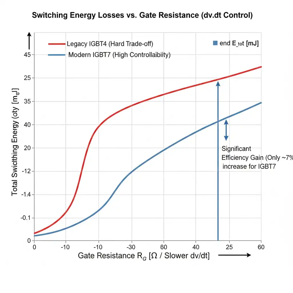 Figure 2: Comparative analysis of Switching Losses (Etot) vs. dv/dt for IGBT4 and IGBT7 technologies.
Key Data Point: Engineering studies and datasheet analyses reveal that with IGBT7, limiting the dv/dt to protect motor insulation (e.g., reducing the slope by 50%) results in a total loss increase of only approximately 7%.
This “7% penalty” is a game-changer. It implies that designers can now prioritize motor reliability and extended cable lengths without needing to oversize the cooling system or move to more expensive semiconductor materials like SiC for standard drives.
System-Level Design Considerations
To fully leverage this controllability, engineers should focus on the following design aspects when integrating modern Power Semiconductors:
1. Gate Driver Selection
While the IGBT itself is controllable, the gate driver must provide precise current control. Using separate gate resistors for turn-on (RG,on) and turn-off (RG,off) is essential. This allows independent optimization of:
- Turn-on (di/dt): Controls Electromagnetic Interference (EMI) and reverse recovery stress on the diode.
- Turn-off (dv/dt): Controls voltage overshoot and motor insulation stress.
2. Cable Length Guidelines
Even with dv/dt control, physical limits remain. For general industrial applications using standard PVC-insulated cables:
- Short Cables (< 10m): High dv/dt is generally acceptable; focus on efficiency.
- Medium Cables (10m – 100m): Moderate dv/dt limiting is required. The IGBT7’s controllability shines here, eliminating the need for bulky dV/dt filters.
- Long Cables (> 100m): Significant dv/dt reduction is necessary. Output reactors or sine-wave filters may still be required alongside gate control.
Conclusion
The conflict between converter efficiency and motor protection is no longer a zero-sum game. With the advent of highly controllable devices like the IGBT7, engineers can design drive systems that are both thermally efficient and gentle on motor insulation.
By utilizing the linear dv/dt characteristics of these modern components, you can precisely tune the switching slopes via the gate resistor. The result is a robust drive system capable of handling longer cables and extending motor life, with a negligible impact on total system losses.
For engineers sourcing components for next-generation drives, selecting modules with superior controllability is the most cost-effective strategy to enhance system reliability.
Next Steps for Your Design
Are you looking to upgrade your inverter designs or source high-performance power modules? Explore our catalog of electronic components to find the right solution for your application. If you need assistance with component selection for specific dv/dt requirements, our engineering team is ready to assist.
For a visual explanation of how these voltage spikes occur in VFD systems, this video provides excellent context:
Recommended Watch:
SMC Tech Tips: Combating Reflected Wave
This video is highly relevant as it visually demonstrates the “Reflected Wave” phenomenon caused by PWM and cable impedance mismatch—the exact problem that the dv/dt controllability discussed in this article aims to solve.