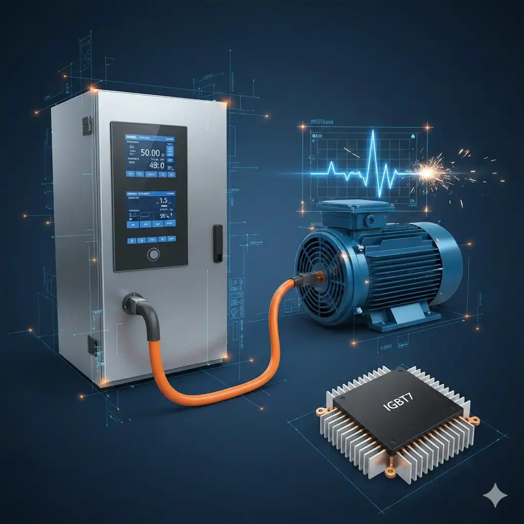
Unlocking Efficiency in Industrial Drives: A Technical Analysis of TRENCHSTOP™ IGBT7 Technology
In the realm of industrial automation and motion control, the Variable Speed Drive (VSD) stands as the primary regulator of energy consumption. As global efficiency standards tighten (such as the EU Ecodesign Directive), power electronics engineers are under increasing pressure to minimize losses in the inverter stage. For over a decade, the 4th generation IGBT (IGBT4) has been the industry workhorse. However, the physical limits of standard trench-gate field-stop technologies have necessitated a structural evolution.
This article provides an engineering-level analysis of Infineon’s TRENCHSTOP™ IGBT7 technology. We will explore how the transition to a Micro-Pattern Trench (MPT) structure fundamentally alters carrier dynamics, enabling a reduction in saturation voltage (Vce(sat)) while maintaining the critical dv/dt controllability required for motor insulation protection.
The Physics of Efficiency: Micro-Pattern Trenches (MPT)
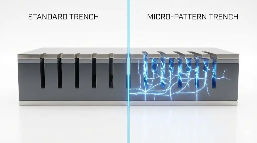
To understand the leap from IGBT4 to IGBT7, one must look at the vertical structure of the chip. Previous generations utilized a standard trench-gate design where the primary optimization lever was thinning the wafer and adjusting the field-stop layer. The IGBT7 introduces the Micro-Pattern Trench (MPT) architecture. Unlike the uniform trench arrays of the past, MPT utilizes a cellular structure with stripe-patterned trenches separated by sub-micron mesas.
The Carrier Storage Effect
The defining advantage of the MPT structure is its ability to drastically increase charge carrier concentration at the emitter side of the drift region. In a standard IGBT, the hole concentration drops as one moves from the collector to the emitter. The MPT geometry creates a barrier that hinders the extraction of holes during the on-state, effectively “storing” carriers near the trench bottom.
This carrier storage effect enhances conductivity modulation, making the drift zone behave as if it were more heavily doped without actually increasing the background doping concentration. The result is a significantly lower on-state voltage drop (Vce(sat)) for the same blocking voltage.
- IGBT4 Nominal Vce(sat): Typically ~2.05V (at 125°C)
- IGBT7 Nominal Vce(sat): Typically ~1.70V (at 125°C)
This reduction of approximately 20% in static losses is critical for applications like general-purpose drives (GPD), where the device spends a significant portion of its duty cycle in conduction mode.
Addressing the dv/dt Dilemma in Motor Drives
While reducing losses is paramount, speed cannot come at the expense of system reliability. A common side effect of newer, faster-switching silicon is an increase in the voltage rate of rise (dv/dt) during switching events. In industrial motor drive applications, an uncontrolled high dv/dt can cause three major issues:
- Insulation Stress: High dv/dt spikes can reflect along long motor cables, doubling the voltage at the motor terminals and degrading the winding insulation.
- Bearing Currents: Capacitive coupling can induce currents in the motor bearings, leading to premature mechanical failure.
- EMI: Excessive switching speeds generate high-frequency electromagnetic interference.
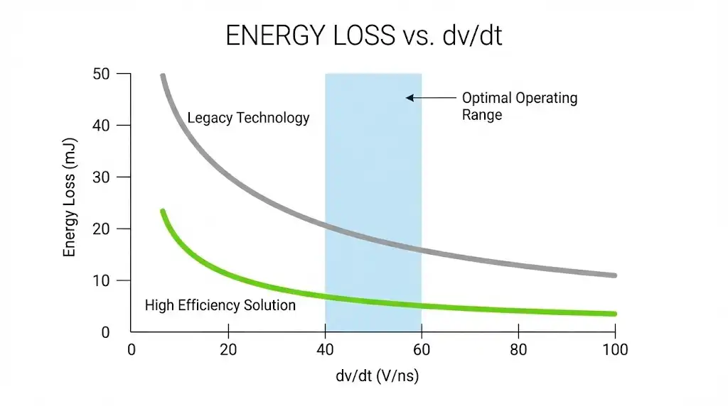
The TRENCHSTOP™ IGBT7 is engineered specifically to operate within a “soft” switching window. While the chip is capable of extremely fast switching, it is optimized for high controllability via the gate resistor (Rg). Engineers can tune the Rg to maintain a typical dv/dt of 5 kV/μs, which is the industry standard “safe zone” for standard non-inverter-duty motors.
Crucially, the MPT structure allows the IGBT7 to maintain low switching losses (Eon and Eoff) even when clamped to this 5 kV/μs limit. This decouples the classic trade-off where slowing down the device (to protect the motor) would previously cause a spike in switching losses.
Thermal Robustness: The 175°C Advantage
Industrial drives often face harsh start-up conditions. For example, a conveyor belt loaded with heavy material may require the motor to draw currents significantly above nominal ratings for several seconds to break static friction (stiction).
The IGBT7 technology features an increased overload capability. While standard continuous operation often remains designed for 150°C to ensure long-term reliability (lifetime bond wire constraints), the IGBT7 is qualified for short-term operation at a junction temperature (Tvj,op) of 175°C under overload conditions.
Engineering Implication: This 25°C thermal headroom allows designers to size the power module based on the nominal current rather than the peak overload current. A smaller module can now handle the start-up spike without exceeding the safe operating area (SOA), leading to significant cost optimization.
System Impact: “Package Jumping” and Power Density
The combination of lower static losses and higher thermal limits enables a substantial increase in power density. In the context of the popular “Easy” module format, this facilitates a concept known as “Package Jumping.”
| Module Platform | IGBT4 Current Rating | IGBT7 Current Rating | Impact |
|---|---|---|---|
| Easy 1B | Up to 15A | Up to 25A | Fits a 25A inverter in a footprint previously limited to 15A. |
| Easy 2B | Up to 50A | Up to 100A | Doubles current capability in the same form factor. |
| EconoDUAL™ 3 | 600A | 900A | Enables 30% higher frame output current. |
For OEMs and integrators, this means a 25A drive that previously required the larger Easy 2B housing can now be built using the compact Easy 1B housing. This reduction in physical size trickles down to the heat sink and enclosure, reducing the overall Bill of Materials (BOM) cost.
Integration with Freewheeling Diodes
An IGBT never operates in isolation. The performance of the freewheeling diode is equally critical, particularly during the commutation loop in half-bridge topologies. The IGBT7 is paired with the EC7 (Emitter-Controlled 7) diode.
The EC7 diode is optimized to prevent “snap-off” during recovery—a phenomenon where the diode current cuts off too abruptly, causing voltage overshoot and ringing. The EC7 provides a softer reverse recovery curve, which reduces EMI generation and allows for the use of lower-rated, less expensive passive filter components at the output.
Conclusion
The transition from IGBT4 to TRENCHSTOP™ IGBT7 is not merely a marketing update; it represents a fundamental shift in chip architecture via Micro-Pattern Trenches. By successfully decoupling saturation voltage from switching speed, and offering a tunable dv/dt centered around 5 kV/μs, this technology addresses the specific pain points of the general-purpose drive market.
For engineers designing the next generation of servo drives, robotics controllers, or industrial inverters, the IGBT7 offers a pathway to increase power density and reduce cooling requirements without compromising the insulation integrity of the driven motor.
At Shunlongwei Co. Ltd, we monitor these semiconductor advancements closely to support our clients in selecting the most robust components for their power electronics supply chain. Understanding the physics behind these devices ensures that we can help you navigate the migration from legacy components to high-efficiency solutions.
References & Further Reading
- Infineon TRENCHSTOP™ IGBT7 Product Overview – Official technical documentation and datasheets.
- Insulated-Gate Bipolar Transistor (IGBT) – Wikipedia – General principles of IGBT operation.
- Generation 7 IGBTs: The New Workhorse – Technical analysis on EEPower.
Content in This Series

Deep Dive into Micro-Pattern Trench (MPT) Technology: The Physics of Loss Suppression in Modern IGBTs