

Content last revised on October 26, 2026
Dual Channel CCFL High Voltage Resonant Inverter Striking Voltage and Ignition Debugging
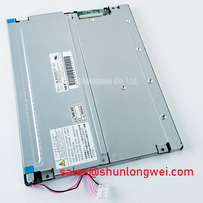
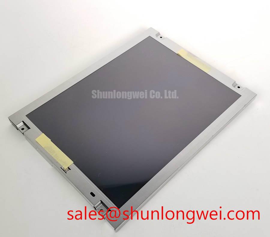
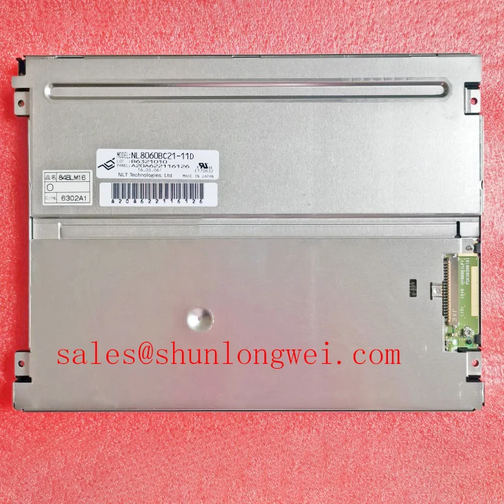
When an AGV or forklift telematics display remains dark, first separate the panel image path from the backlight path: inspect the display connector, confirm the host controller is operating, and observe whether the screen produces a faint image under controlled illumination. The NEC NL8060BC21-11D is a TFT-LCD active matrix color display module; the original equipment documentation must define its installed backlight arrangement and electrical interface.
For legacy equipment using a dual-channel CCFL inverter, cold ignition behavior is controlled by the inverter transformer, lamp condition, wiring insulation, and the controller’s protection sequence. A high-voltage strike value discussed for a replacement inverter, including a possible 1500 to 1650 Vrms ignition range, is a system-level design value rather than an official rating of this NEC display module. The repair engineer should compare the original inverter specification, lamp configuration, enable timing, and fault feedback before applying power.
In a practical bench check, monitor whether both lamp channels start together and whether the inverter enters protection after an uneven ignition event. Audible buzz can originate from transformer magnetics, loose mechanical parts, switching frequency interaction, or an unstable lamp load. Do not attribute the sound to the LCD panel without isolating the inverter and backlight harness. If the replacement system uses an LED conversion kit, its constant-current driver, dimming input, thermal behavior, and optical output must be evaluated as a new backlight system rather than assumed to match the original CCFL assembly.
LED service documentation often refers to a 50,000-hour point at which brightness may reach a specified fraction of initial output. Such a lifetime figure applies only under the conditions supported by the relevant LED, driver, and thermal data; it should not be treated as a published lifetime claim for the NL8060BC21-11D. For an industrial repair, record initial luminance, operating temperature, dimming condition, and driver current so later brightness changes can be compared objectively.
⚠️ Field Alert: Disconnect power before releasing or inserting the display or inverter connector, because live insertion can expose signal and backlight contacts to unintended electrical stress. CCFL inverters generate hazardous high voltages; energized measurements require qualified personnel and appropriately rated probes.
Suppressing Pixel Jitter and Horizontal White Lines Induced by Adjacent 400V Motor Drives
Pixel jitter and horizontal white bands near a variable frequency drive should be approached as a signal integrity and grounding investigation, not as proof of panel failure. Route the display cable away from motor output conductors, inspect the connector locking condition, and compare the affected image with the motor drive stopped and then operating under load. The result helps distinguish conducted interference, radiated coupling, and a display timing problem.
A shielded FFC or LVDS cable can reduce unwanted coupling when its shield termination is compatible with the host chassis and panel assembly. The correct termination method is system dependent: an inappropriate shield connection can create a circulating current path or shift the reference potential. Common-mode ferrite suppression may be considered on the cable assembly when testing shows common-mode noise, but its impedance characteristics must be checked against the transmitter edge rate and the required data bandwidth.
TTL and LVDS are not interchangeable merely because both carry display timing information. Verify the transmitter standard, pin or differential pair assignment, clock polarity, data mapping, and receiver requirements from the original equipment drawings. Clock jitter and data hold margin should be measured at the receiving interface across the intended industrial temperature range, with the cable installed in its final routing position. A clean image on a short bench cable does not prove adequate margin inside a drive cabinet.
Use an oscilloscope with suitable probing practices to compare a known-good signal path with the affected unit. Look for common-mode movement, ringing, intermittent clock edges, and data transitions that change when the motor drive accelerates. The NL6448BC20-35D may be reviewed as a related display solution within a broader equipment architecture, but electrical and mechanical compatibility must be evaluated from the target system documentation rather than assumed from product family naming.
Polarizer Durability and Optical Retardation Film Inspection under Direct Industrial Lighting
Direct sunlight and high bay lighting can make a working display appear defective when the actual issue is viewing angle, surface reflection, or reduced perceived contrast. Inspect the NL8060BC21-11D from the operator’s normal position, then vary the viewing angle vertically and horizontally while displaying a neutral gray image. Record whether the change is uniform across the screen or localized to one region.
TN, IPS, and MVA optical behavior differs substantially, so a viewing cone such as 85 degrees in four directions must not be assigned to this model without a matching manufacturer specification. The same caution applies to contrast values under 50,000 lux illumination. Such ambient-light measurements describe an optical system under specific evaluation conditions and should not be treated as confirmed factory ratings for this module without supporting documentation. Designers should judge readability using the actual cover window, bezel depth, ambient illumination, and operator position.
Surface anti-glare treatment can reduce mirror-like reflections, but it may also alter perceived sharpness and black level when viewed under oblique lighting. Inspect the surface with diffuse light first, then use a narrow inspection light to identify scratches, pressure marks, coating irregularity, or contamination. Do not use aggressive solvents or abrasive wipes on the polarizer. Follow the equipment manufacturer’s approved cleaning method and keep cloth pressure low around the active viewing area.
For a replacement evaluation, compare a white field, mid-gray field, and black field under the same illumination. Optical retardation or polarizer damage may appear as colored patches, angle-dependent contrast changes, or localized darkening. These observations require comparison with a known-good unit because ambient light, camera exposure, and the cover glass can create similar visual impressions. General industrial TFT principles are discussed in The Ultimate Guide to Industrial TFT LCD Technology.
Full Screen Primary Color AOI Screening: Stuck Sub Pixels and Background Uniformity Audit
Run a full-screen red, green, blue, white, black, and neutral gray sequence before installing the panel into an AGV or forklift console. A primary-color test helps locate stuck sub-pixels, inactive areas, vertical artifacts, and nonuniform brightness. Keep the test image stable long enough for the technician to inspect the complete active area, then repeat it after the display has reached its normal operating condition.
An inspection using a flashlight held at approximately 45 degrees can help reveal a faint image when the backlight is not working. Changes in a shadow with illumination angle alone do not establish a backlight fault; inspect the backlight, diffuser path, bezel pressure, and optical surface as appropriate. If a sharp line remains fixed on the screen across different test images, examine the display data path, connector seating, and controller timing. A localized line may also require inspection of the panel edge and bonded driver region, but it should not be assigned to a microscopic internal fracture without comparative evidence.
Power sequencing deserves the same attention as image quality. The host controller, display supply, enable signal, and backlight command should follow the original equipment sequence. White-screen startup, residual images during shutdown, or intermittent recovery can result from an incorrect order, an unstable supply, or a controller that continues sending data while the panel supply is collapsing. The system integrator should verify the required supply voltage and timing from the original panel documentation.
When an LED driver uses PWM dimming, evaluate the selected frequency and duty-cycle response against the driver specification, camera interaction, visual flicker sensitivity, and acoustic behavior. A nominal range such as 200 Hz to 1 kHz belongs to the driver and system evaluation, not to the confirmed factory data for this NEC module. Check brightness linearity at several command levels and observe the screen through the equipment’s normal viewing position.
Long-term static HMI screens should use the host system’s approved screen-management strategy, such as controlled content changes or reduced luminance where appropriate. This is a system design consideration rather than a guaranteed panel protection function. For a broader display selection assessment, engineers may also review NL6448BC33-24 as a separate device, subject to size, resolution, connector, timing, optical, mechanical, and power compatibility checks.