

Content last revised on October 4, 2026
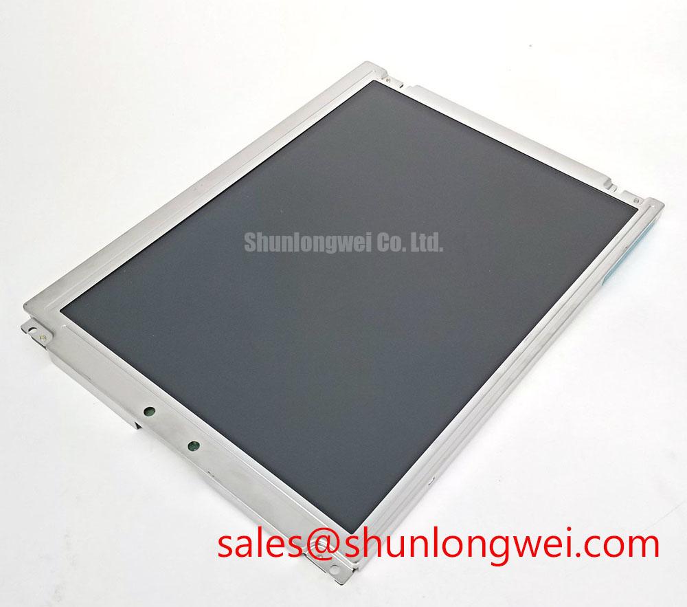
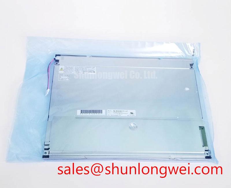
NEC NL6448BC33-24 TFT-LCD Industrial HMI Panel
Begin incoming inspection by comparing the NL6448BC33-24 marking with the equipment service record, then examine the TFT-LCD module for cracked glass, bezel distortion, connector damage, contamination, and visible pressure marks before applying power. This initial check protects the test result from mechanical damage being mistaken for an electrical or optical fault.
The NEC NL6448BC33-24 is identified in the supplied product information as an industrial-grade LCD/HMI panel with a TFT-LCD display module construction. Interface pin assignment, display resolution, active-area dimensions, optical performance, backlight type, supply requirements, and operating-temperature limits should be checked against the original panel documentation before installation.
| Product identification | NL6448BC33-24 |
| Manufacturer | NEC |
| Product category | Industrial Grade LCD/HMI Panel |
| Module construction | TFT-LCD Display Module |
For a repair department, this distinction matters. A replacement display must match more than its external outline. The engineer should confirm the host controller interface, power sequence, backlight control method, connector orientation, mounting points, active image area, and environmental ratings from the source equipment documentation. A visually similar panel can still be electrically incompatible if its timing, pinout, backlight driver, or mechanical reference points differ.
Viewing-Angle Inspection for Multi-Angle Consoles
During incoming optical inspection, display the same neutral gray, white, black, and saturated color fields while viewing the panel from the intended operator positions. Record changes in luminance, contrast impression, grayscale separation, and color balance rather than judging the panel from a single perpendicular position. This is particularly relevant when the LCD is evaluated for a railway passenger information system or cab signalling display, where the screen may be viewed from an offset console position.
The supplied factory data does not confirm a specific Super-IPS or MVA designation, nor does it provide a verified 85°/85°/85°/85° viewing-angle specification. Those values must not be assigned to the NL6448BC33-24 without the applicable NEC datasheet. The correct engineering method is to compare the replacement against the original panel under the same viewing geometry and illumination. If the equipment documentation specifies a symmetric viewing cone, the integrator should confirm the relevant horizontal and vertical viewing-angle definitions, measurement contrast ratio, and grayscale conditions.
Surface treatment also requires practical inspection. Under strong ambient light, an anti-glare surface can reduce reflected images, but it may alter perceived sharpness, black-level appearance, or fine text contrast. The service technician should inspect the panel with the actual screen graphics used by the equipment, including small fonts, warning symbols, and high-density status pages. A uniform white field can reveal broad luminance variation, while a dark field can expose localized bright areas, edge leakage, or pressure-related optical marks.
PWM dimming behavior should be treated as a system verification item. The provided model information does not confirm a 200 Hz to 1 kHz dimming frequency range or a particular duty-cycle linearity. If the host system controls brightness by PWM, the engineer should measure the backlight-control waveform with an oscilloscope and observe the screen through a camera capable of detecting modulation. The purpose is to identify visible flicker, beat effects, or unexpected brightness steps under the actual controller settings. The final frequency, polarity, amplitude, and duty-cycle limits remain system-determined unless they are explicitly listed in the original panel documentation.
When a same-size or same-resolution comparison is required, engineers may review NL10276BC16-06 as a separate display option. It should be evaluated independently; mechanical similarity does not establish electrical, optical, or functional interchangeability.
Backlight Driving, PWM Dimming, and Flicker Control
Do not connect a replacement panel to an unknown backlight source simply because the connector appears compatible. First identify whether the original assembly uses an integrated backlight circuit or requires an external driver, then verify the host voltage, current regulation method, enable signal, dimming input, connector pinout, and startup sequence from the equipment service documentation. The supplied factory information does not confirm that this particular model uses WLED, constant-current driving, a 1000:1 PWM dimming ratio, or a defined backlight lifetime.
This distinction is important when an older display is being considered for a railway PIS terminal or a cab display. A cold-cathode fluorescent backlight system and an LED backlight system require different driver architectures, safety controls, and brightness interfaces. The high-voltage ignition requirements associated with CCFL assemblies must not be applied to this NEC model unless the original documentation identifies that architecture. Likewise, a WLED assumption should not be made without a confirmed part-level or equipment-level specification.
For an LED-based host system, constant-current regulation is normally assessed by observing current stability during brightness changes, startup, warm operation, and low-brightness operation. This is a Design Consideration, not a confirmed NL6448BC33-24 factory parameter. The test engineer should check whether the display remains free of periodic brightness bands, audible driver noise, unstable startup, or abrupt transitions when the controller changes its brightness command. A photodiode or calibrated luminance instrument can help separate real optical modulation from camera artifacts.
The requested claim of more than 50,000 hours of half-life or MTBF cannot be assigned to this model from the supplied factory data. Lifetime depends on the specified backlight technology, drive current, temperature, thermal path, brightness setting, and test definition. If a procurement specification requires a half-life or MTBF value, the buyer should request the relevant manufacturer document and confirm whether the figure refers to LED lumen maintenance, panel operation, or a statistical reliability calculation.
Direct sunlight testing should also be described carefully. The supplied information does not verify a contrast ratio above 500:1 at 50,000 lux. A field evaluation can place the panel under representative ambient illumination and compare legibility of the actual equipment graphics, but this is an application test rather than a factory rating. The enclosure window, viewing angle, surface reflection, image content, and automatic brightness controls all influence the result.
The display chain may include a separate companion solution such as NL6448BC30-24D. That reference should be treated as a separate product and assessed for its own electrical and optical documentation rather than assumed to be a required accessory for the NL6448BC33-24.
Mechanical Pressure Control and Signal Integrity on Dark Screen Fields
Dark-field inspection is useful after the panel has been mounted in its equipment bezel. Display a uniform black image, allow the assembly to reach a stable operating condition, and inspect the corners, edges, connector side, and fastener regions from the normal viewing position. Localized bright areas or dark patches can have several possible causes, including panel pressure, bezel contact, optical non-uniformity, signal behavior, or source-image conditions. The technician should compare the result with an unmounted or known-good reference before assigning a cause.
The supplied factory information does not provide a chassis envelope tolerance, light-guide-plate construction, cross-pattern fastener specification, or an approved M3 torque range of 0.35–0.45 N·m. Those values must not be presented as NEC limits for this model. As a Design Consideration, the mounting frame should support the panel without point loading, twisting, or forcing the bezel against the active display area. The final fastener type, tightening sequence, compression allowance, and torque must be established from the equipment mechanical drawing and validated with a post-assembly optical inspection.
Mechanical work should be followed by an interface check. Confirm that the cable enters the connector without lateral force, that the locking feature is fully engaged, and that the cable bend does not transfer load into the panel connector. Power should remain removed during connector handling, and the technician should use suitable ESD controls. Bench Tip: keep the flex cable square to the connector and fully release power before insertion or removal to reduce avoidable contact and ESD damage.
The model information supplied here does not confirm TTL or LVDS signaling, transmitter clock limits, jitter tolerance, setup time, or data hold time. The integrator should therefore identify the actual interface from the original NEC documentation and the host controller schematic. During troubleshooting, compare clock and data activity with a known-good panel or a verified reference waveform. An unstable image, intermittent line, or missing region may involve timing, cable integrity, connector seating, controller configuration, power sequencing, or panel damage; it should not be reduced to one assumed cause without measurement.
Where the host uses a differential display interface, the system designer should control the signal return path and minimize unnecessary cable discontinuities. The acceptable eye opening, common-mode range, termination arrangement, and clock margin are determined by the transmitter, receiver, cable, and panel interface specification. These values require bench validation at the operating temperature and supply conditions relevant to the equipment.
Thermal Cycling, Cold-Start Response, and Perimeter Seal Integrity
Before approving a replacement for a wide-temperature industrial installation, run a controlled visual and functional check at the temperatures defined by the original equipment specification. Observe startup behavior, gray-level transitions, text clarity, backlight stability, and image retention during the transition from cold to normal operation. The supplied factory information does not state a verified operating range of −30°C to +85°C, a gray-to-gray response specification, or a thermal-cycle qualification for this model.
Liquid-crystal response can change with temperature, but the magnitude and acceptable compensation method depend on the panel construction, drive electronics, image mode, and host timing. Any cold-start delay or gray-level response change should be measured against the equipment acceptance criteria rather than corrected with an assumed universal timing value. Designers should verify power sequencing, controller initialization, backlight enable timing, and image refresh behavior under the documented environmental limits.
Mechanical expansion between the display module, bezel, mounting frame, and equipment enclosure can also influence optical uniformity. Inspect the perimeter after thermal exposure for frame interference, connector strain, visible pressure patterns, or changes in the seal area. The available product data does not confirm a particular epoxy sealant, gasket compound, adhesive system, or resistance to a specified number of thermal cycles. Claims about seal integrity should therefore be supported by the applicable NEC reliability documentation or by a system-level qualification test.
For installations exposed to vibration or repeated temperature changes, the enclosure designer should provide controlled support without transferring enclosure deformation into the display glass or connector. This is a Design Consideration; it is not a model-specific certification. Railway equipment teams should verify the complete assembly against their own vibration, shock, ingress, thermal, and electromagnetic requirements. The LCD module itself should not be described as independently certified for whole-equipment EMC or safety compliance.
Additional practical evaluation guidance is available in Industrial Display & HMI Solutions. Use that material as an engineering reference while checking the actual enclosure, cable routing, optical window, thermal path, and service procedure for the target equipment.