

Content last revised on October 2, 2026
Eye-Diagram Voltage Margin & Differential Noise Floor Verification in High-Vibration Bays
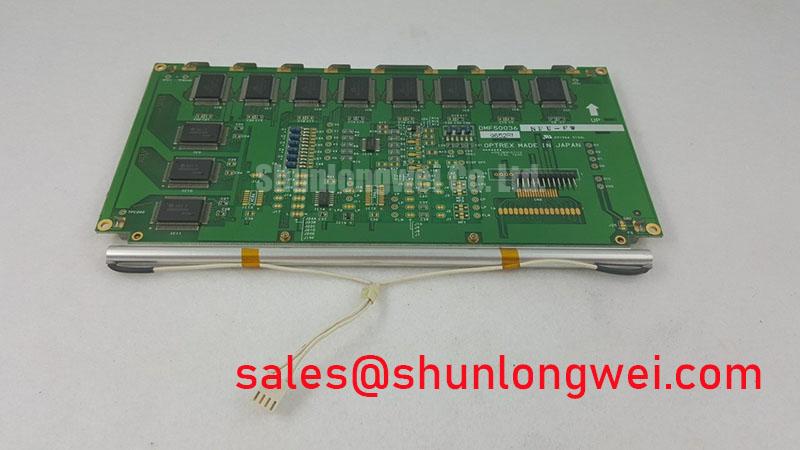
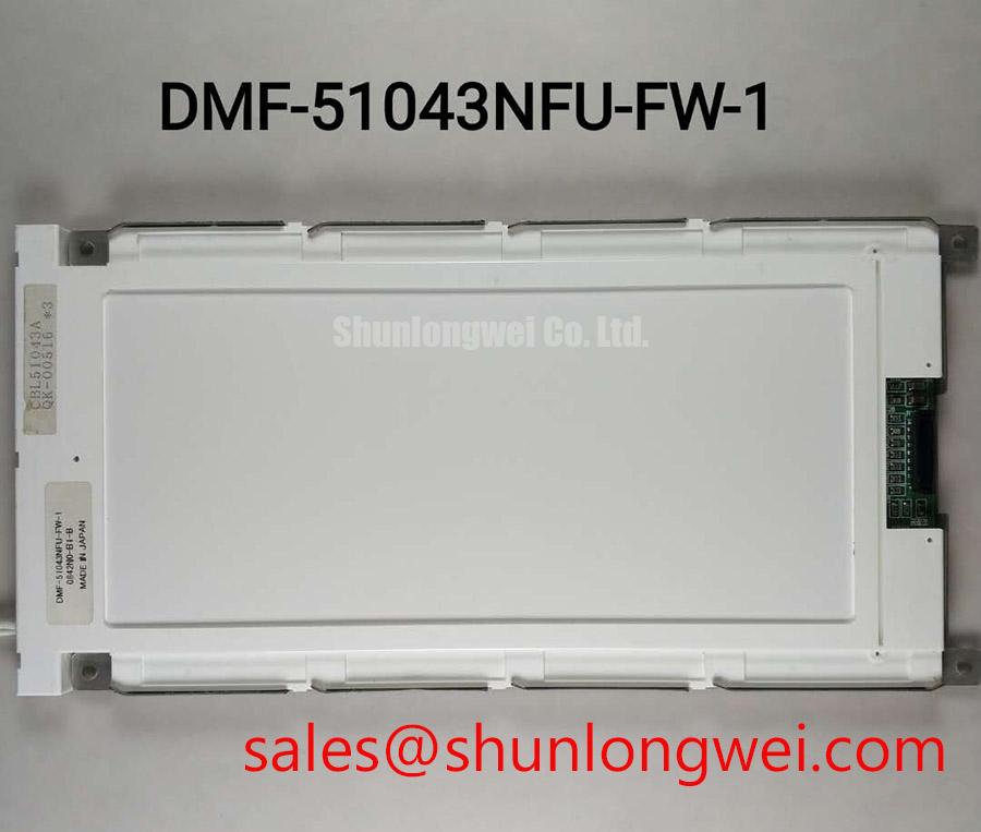
Begin the replacement inspection by comparing the installed module label with DMF-51043NFU-FW-1, then check the TFT-LCD assembly for cracked glass, frame distortion, connector damage, and contamination before applying power. The supplied factory information identifies this unit as a Kyocera / OPTREX Industrial Grade LCD/HMI Panel in a TFT-LCD Display Module package. Its specification status is recorded as Official Factory Spec Verified. Electrical interface details, optical ratings, dimensions, power requirements, and environmental limits should be confirmed against the original panel documentation before installation.
| Manufacturer | Kyocera / OPTREX |
| Model | DMF-51043NFU-FW-1 |
| Product category | Industrial Grade LCD/HMI Panel |
| Package type | TFT-LCD Display Module |
| Specification status | Official Factory Spec Verified |
For an AGV or forklift telematics repair, physical compatibility is only the first checkpoint. The system integrator should verify the display connector, signaling method, pin assignment, supply voltage, backlight control method, mounting envelope, and controller timing from the equipment service documentation. The information supplied for this model does not confirm a specific LVDS or TTL interface, a fixed backlight topology, a viewing angle, a response time, or a defined operating temperature range. Those values should not be inferred from the product category alone.
After the replacement panel is mechanically positioned, inspect the cable route before connecting the display. AGV and forklift telematics assemblies can place the display cable near motor controllers, switching converters, brake actuators, and other sources of common-mode interference. The correct cable arrangement depends on the original equipment design, but the general engineering objective is clear: maintain a controlled signal return path and prevent the display harness from sharing high-current switching paths.
If the host system uses LVDS, the engineer should identify the exact pair assignment and compare the installed cable construction with the original harness. A differential interface relies on balanced conductors, consistent pair geometry, and an appropriate termination arrangement. A nominal differential impedance such as 100 ohms is a common system design consideration for LVDS links, not an official specification confirmed here for DMF-51043NFU-FW-1. The system designer must verify the host transmitter, receiver, cable, and termination requirements as one signal path rather than selecting a value from the display category.
For TTL systems, the inspection priorities change. Single-ended data and clock lines are more sensitive to shared ground movement and coupling from adjacent conductors. The replacement procedure should therefore include a comparison of logic levels, clock polarity, data order, pixel format, and enable timing against a known-good display assembly. If the host uses LVDS, examine the eye opening at the receiver under the actual cable routing and vibration condition. If the host uses TTL, observe clock and data transitions at the panel connector and confirm that the timing relationship remains stable during display activity.
Common-mode ferrite components should not be added automatically. Their suitability depends on the cable construction, switching spectrum, signal edge rate, and the system’s conducted noise behavior. An unsuitable component can increase insertion loss or alter the differential balance. A Design Consideration is to evaluate any shielding or filtering change with the complete harness installed, including chassis bonding and connector backshells. A 360 degree shield termination may be appropriate in some industrial cable assemblies, but the mechanical connector design and equipment grounding scheme determine whether it improves or worsens the overall noise path.
When horizontal noise bands, intermittent pixels, or unstable image updates appear, avoid assigning the symptom to the panel alone. First compare the signal at the host output and at the display input, then inspect the ground reference, connector retention, pair continuity, and cable movement sensitivity. An oscilloscope or suitable differential probe can help reveal clock jitter, common-mode movement, or a deteriorated eye pattern. The The Ultimate Guide to Industrial TFT LCD Technology provides broader background for interpreting these signal integrity checks.
💡 Pro Tip: Keep differential pairs routed as a matched group with a continuous return reference, and disconnect power before reseating the display cable.
Constant Luminance Output Control & L70/B50 LED Reliability Verification
The supplied factory data classifies this product as a TFT-LCD display module but does not state the backlight source, LED current, luminance, dimming frequency, L70 value, B50 value, or rated backlight life. These details must be confirmed from the original Kyocera or OPTREX documentation for the exact suffix. The system integrator should verify whether the host provides a dedicated backlight supply, an enable signal, analog control, PWM control, or another manufacturer-defined interface before connecting a replacement unit.
Backlight troubleshooting should start with the symptom and the complete power path. A dark image may result from an inactive backlight command, an incorrect supply condition, a connector problem, a protection response, or a display controller issue. Measure the host-side backlight output using the equipment service procedure, then compare it with the replacement module requirements. Do not apply an assumed voltage or current based on another display with a similar diagonal size or connector shape.
For a PWM-controlled system, the engineer should verify the host frequency, duty-cycle behavior, enable timing, and control polarity against the panel documentation. A frequency range such as 200 Hz to 1 kHz is sometimes used as a general starting point in display system design, but it is not an official specification for this model. The correct setting is determined by the backlight driver, optical requirements, camera interaction, audible behavior, and the display controller. Flicker evaluation should be performed at the actual luminance setting used by the AGV or forklift terminal, not only at full brightness.
Thermal inspection is also important when a narrow bezel or sealed telematics enclosure is used. A rail, bracket, or gasket that presses against the display edge can obstruct intended heat paths or create local mechanical stress. Any heat spreader should be evaluated for electrical clearance, weight, vibration loading, and contact pressure. It should not be assumed that an aluminum rail, optical bonding layer, light guide construction, or diffuser material is present in this specific module unless the manufacturer documentation confirms it.
L70 and B50 are reliability metrics that require a defined test method, temperature condition, drive current, and statistical interpretation. No such values are provided in the available factory parameter set for DMF-51043NFU-FW-1. A procurement review should request the applicable backlight reliability data if long operating intervals or high ambient brightness are essential to the equipment. In the field, compare luminance uniformity across the screen, inspect for edge darkening, and record whether the defect follows the panel, driver, cable, or enclosure position.
For AGV and forklift installations, the brightness control should be assessed together with the ambient-light sensor and user interface software. Excessive software dimming can resemble a backlight fault, while an unstable control line can produce visible modulation without a permanent panel defect. A controlled substitution using the original harness and a documented host configuration is more reliable than changing several parameters at once.
Super IPS / MVA Wide Symmetric Viewing Cone for Multi-Angle Consoles
The available official product information does not identify the liquid-crystal mode, viewing-angle specification, surface treatment, contrast ratio, gray-scale response, or optical bonding construction of DMF-51043NFU-FW-1. Terms such as Super IPS, MVA, anti-glare, and a symmetric 85 degree viewing cone should therefore be treated as evaluation criteria rather than confirmed attributes of this model.
For a display mounted in an AGV cabin or forklift console, assess the image from the operator’s normal viewing positions rather than from the centerline alone. Check black-level stability, color shift, gray-scale inversion, and legibility of warning text while the operator’s head position changes. TN, IPS, and MVA panels can show different angular behavior, but the actual performance depends on the specific cell, polarizer, cover surface, drive waveform, and viewing environment. A panel family name by itself is not enough to establish compatibility.
Display testing should include the host timing configuration. Verify pixel format, color order, data mapping, clock polarity, frame timing, and power sequencing against the original panel documentation. If the host expects JEIDA data mapping and the replacement path uses VESA mapping, the image can show incorrect colors or abnormal gradation even when the connector fits. The reverse condition can produce a similar integration problem. These mappings must be checked from the controller and panel records, not inferred from the model name.
Gray-scale performance should be checked using the actual T-CON configuration and gamma table. A display may show a usable test pattern while still producing poor low-gray separation, crushed dark detail, or visible contouring in application screens. When the controller allows gamma adjustment, record the original values before changing them. Adjustments should be made only after the signal format, timing, supply conditions, and panel identification have been confirmed.
Surface glare is a system-level concern. A glossy cover, an anti-glare treatment, a protective window, and an optical bonding arrangement each affect reflections differently. The supplied specifications do not confirm which of these features applies to this model. Evaluate the complete installed stack under warehouse lighting, outdoor spill light, and the operator’s expected line of sight. A protective cover can also change touch performance, contrast perception, and the apparent viewing angle.
When the display is intended for multi-angle observation, document the acceptance condition in observable terms such as readable warning text, stable color coding, and preserved status icons. Avoid treating a broad viewing-angle number as a substitute for a full installation test. The display may be suitable for a particular console only after the mechanical cover, controller settings, illumination, and operator position have been evaluated together.
Thermal Expansion Clearance Sizing across Heavy Industrial Metal Enclosure Cutouts
Before fastening the module into a metal enclosure, compare the replacement frame, bezel opening, connector clearance, cable bend path, and fastening locations with the removed unit. The supplied factory parameter set does not include the external dimensions, cutout size, fastener pattern, bezel tolerance, mounting-hole diameter, or allowable clamping load for DMF-51043NFU-FW-1. These measurements must be taken from the equipment drawing or the original module before machining or modifying the enclosure.
A heavy metal panel can transfer vibration and thermal movement directly into the display frame. The installation should preserve the manufacturer’s intended support points while avoiding concentrated pressure on the visible area. A general Design Consideration for compact display assemblies is to use an even cross-pattern fastening sequence and to let the equipment drawing determine the final torque. The supplied information does not confirm an M3 torque limit of 0.35 to 0.45 N·m for this model, so that value must not be treated as a product specification.
Check the cutout after the enclosure has reached its normal operating condition. Paint thickness, gasket compression, burrs, and frame distortion can reduce clearance around the display. The panel should not be forced into an opening that is slightly undersized, and the bezel should not be used to correct a misaligned chassis. If the installation includes a front protective window, verify that it does not touch the display surface when the enclosure flexes.
Low-temperature behavior also requires documentation-based verification. The available factory information does not confirm a rated operating range of minus 20 to minus 30 degrees Celsius, LC response time, heater requirement, or cold-start sequence for this model. At low temperature, liquid-crystal response can change and the host timing may require a defined startup procedure. Designers should verify the specified operating range, warm-up behavior, heater control, and condensation precautions using the original panel documentation and the equipment environmental test plan.
During fault isolation, separate optical symptoms from mechanical symptoms. Dark-field mura, uneven brightness, or a localized image change may be associated with frame stress, cable loading, enclosure pressure, temperature gradients, or display electronics. Inspect the module before and after controlled fastening, compare the image with the panel outside the enclosure, and use the same signal source for both checks. This process helps identify whether the issue follows the module, the mounting condition, or the host system without assigning a single cause prematurely.
Final installation approval should record the verified connector interface, supply requirements, backlight control method, signal mapping, mounting geometry, environmental limits, and display test results. Any value not stated in the official documentation for DMF-51043NFU-FW-1 should remain a system verification item rather than being copied from a visually similar LCD module.