

Content last revised on September 20, 2026
Transient Dynamics & Electrical Design: I2t Sub-Cycle Melting Rating on SKKT 132/12E
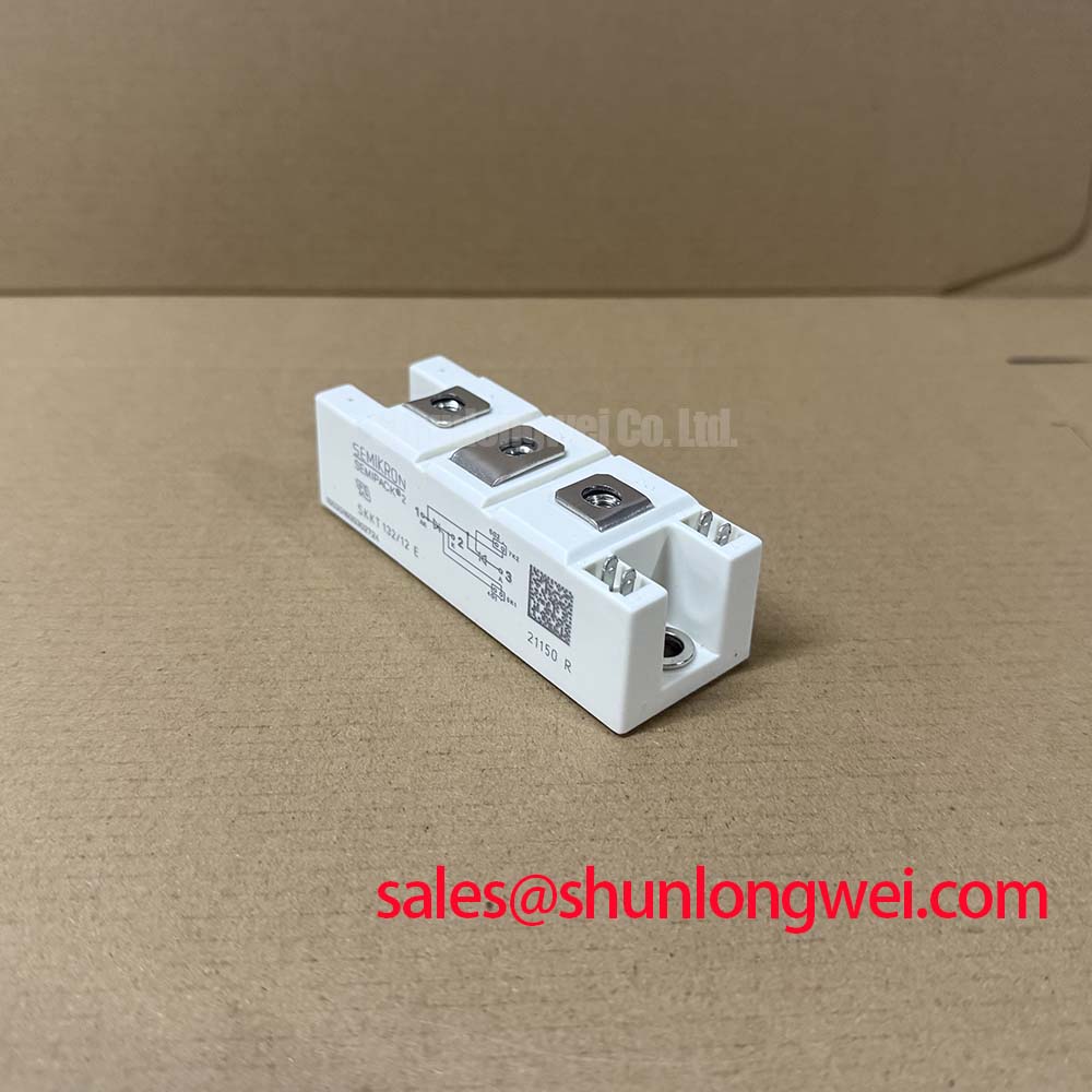
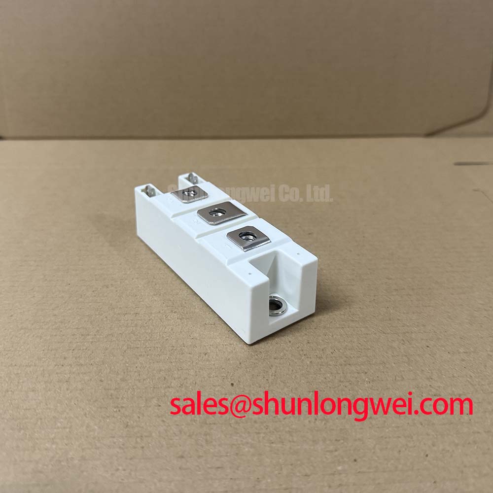
With the power circuit isolated, first verify the terminal designations against the equipment schematic and compare cold-state diode-mode readings between corresponding thyristor paths before connecting a replacement SKKT 132/12E. The module is rated at VRRM = 1200 V and ITAV = 137 A at TC = 85°C, both Official Datasheet Specifications. Its specified ITSM = 2600 A identifies short-duration surge-current capability, but it must not be treated as a substitute for coordinated semiconductor fuse protection during a hard short circuit.
For fuse coordination, the service engineer should obtain the prospective fault current and the fuse manufacturer’s pre-arcing and total clearing I²t data. Those values must be checked against the applicable thyristor surge-current and overload information in the original Semikron documentation. A fuse with an unsuitable clearing characteristic can leave excessive energy in the module even when the nominal current rating appears acceptable. This is a Design Consideration, because system source impedance, transformer capacity, cable length, and branch configuration determine the actual fault energy.
Inspect power terminals for looseness, heat discoloration, damaged thread engagement, or cable lug misalignment. The module mounting and terminal tightening torque must be taken from the applicable mechanical documentation for the installed hardware rather than assumed from a generic package value. ⚡ Safety Interlock Note: De-energize, lock out, and verify the DC and AC power paths are discharged before removing gate or power connections.
💡 Bench Tip: Use ESD-controlled handling and record cold-state readings from a known-good circuit position when available, because comparison is more reliable than assigning a universal diode-mode voltage to a thyristor module.
SKKT 132/12E Operational Boundaries: Evaluating Phase-Angle Voltage Profiling
In a high-voltage three-phase motor solid-state soft starter, the SKKT 132/12E can be evaluated as part of a phase-angle controlled power path where firing timing is used to manage motor acceleration current. The often stated objective of reducing locked-rotor current from six to eight times rated current toward less than 2.5 times rated current is a system control target, not an Official Datasheet Specification of this module. Motor load inertia, supply stiffness, bypass-contactor sequence, current feedback quality, and firing-angle ramp all affect the result.
The 1200 V repetitive peak reverse-voltage rating should be checked against measured line conditions, switching transients, and the installed protection network. The 137 A average on-state current rating at 85°C case temperature also requires evaluation at the actual heatsink temperature rather than ambient cabinet temperature. When integrating a replacement module, designers should verify that the original firing board presents the intended gate connections and that the terminal arrangement matches the existing topology.
Where a higher-current Semikron module is being assessed during a repair review, the SKKD162/12 can be reviewed as a separate electrical and mechanical reference. It is not an automatic substitute: polarity arrangement, gate-drive interface, thermal path, protection coordination, and physical mounting must be confirmed by the system engineer.
Field Diagnostics & Commissioning: Junction-to-Heatsink Heat Dissipation in SKKT 132/12E Topologies
The Official Datasheet Specification for thermal resistance from junction to case is Rth(j-c) = 0.24 K/W per thyristor. This figure describes the semiconductor-to-case thermal path; it does not include thermal interface material, heatsink performance, airflow, enclosure temperature, or load cycle. The stated maximum junction temperature of 125°C is the upper semiconductor boundary that must be evaluated through the complete thermal stack.
Before commissioning, clean the heatsink contact surface, check it for burrs or localized damage, and apply thermal interface material according to the material supplier’s instructions. Tighten mounting hardware progressively and evenly so the module base is supported without distortion. Uneven contact pressure can produce inconsistent thermal transfer and may show up as unequal heating across phases, but temperature imbalance should be investigated alongside firing symmetry, cable resistance, load condition, and airflow.
During controlled operation, compare heatsink temperatures under similar phase loading and inspect the firing waveform against a known-good channel when possible. A rising temperature trend does not establish one isolated cause. It may indicate degraded interface contact, an overloaded phase, abnormal triggering, restricted cooling, or a changed operating duty. For broader power-stage integration practices, including switching and thermal verification principles, consult IGBT Design & Integration.
SKKT 132/12E Circuit Protection & Reliability: Calibrating Surge Energy Dissipation and Voltage Clamping
The module provides Visol = 2500 V AC for 1 minute at 50 Hz as an Official Datasheet Specification. This is an isolation test rating and should not be interpreted as a complete system insulation-coordination or surge-immunity declaration. Clearance, creepage, cabinet wiring, earthing, and insulation condition remain system-level responsibilities.
For heavy-duty AC input protection, engineers should assess the incoming surge environment and verify the coordinated behavior of MOVs, RC snubbers, fuses, contactors, and cable routing. The objective is to limit transient stress across the thyristor paths while avoiding protection parts that introduce unacceptable leakage, heating, or unintended interaction with phase-angle control. Clamp selection and snubber values must be established by measured transient behavior in the finished equipment, verifying peak voltage margins against the applicable 1200 V repetitive blocking ratings.
Reference material for the applicable Semikron SEMIPACK® thyristor and diode module family is useful when confirming module-family handling and integration context. In systems using separate high-current thyristor sections upstream or in adjacent controlled branches, the SKKT273/12E is a related module reference that should be evaluated independently against the original circuit documentation.