The Critical Role of 1200V IGBTs in Modern Industrial Drives
In the world of industrial automation, from robotic servo drives to large-scale variable frequency drives (VFDs), the 1200V Insulated Gate Bipolar Transistor (IGBT) module stands as a true workhorse. This voltage class is perfectly suited for systems running on standard 380V or 400V three-phase AC lines, providing the necessary voltage headroom for safe and reliable operation. However, for design engineers, selecting the right 1200V IGBT is a complex balancing act. The core challenge lies in navigating the trade-offs between performance, thermal stability, and, most importantly, energy efficiency. The key to mastering this challenge is to understand two fundamental parameters from the datasheet: the collector-emitter saturation voltage, Vce(sat), and the switching energies, Eon (turn-on) and Eoff (turn-off). These values are not just numbers; they are the DNA of an inverter’s efficiency and thermal behavior.
Decoding the DNA of Inverter Losses: Vce(sat) and Eon/Eoff Explained
Every watt of energy lost in an IGBT module is converted into heat, which must be managed. These losses primarily fall into two categories: conduction losses and switching losses. Understanding their origins is the first step toward optimization.
Vce(sat) – The Conduction Loss Factor
Vce(sat) represents the voltage drop across the IGBT’s collector and emitter terminals when it is fully “on” and conducting current. Think of it as the inherent resistance of the switch. This voltage drop directly leads to conduction losses, which can be estimated with a simple formula: P_cond ≈ Vce(sat) × I_c × D, where I_c is the collector current and D is the duty cycle. A lower Vce(sat) means less power is wasted as heat during the on-state. Modern technologies like Trench-Gate and Field-Stop (TFS) structures have been engineered to minimize this saturation voltage, significantly boosting efficiency in applications where the IGBT spends a large portion of its time conducting high current.
Eon & Eoff – The Switching Loss Culprits
Unlike conduction losses, switching losses occur during the brief moments the IGBT transitions between the on and off states. Eon is the energy consumed to turn the device on, and Eoff is the energy lost when turning it off. Total switching power loss is calculated as: P_sw ≈ (Eon + Eoff) × f_sw, where f_sw is the switching frequency. As the frequency of switching increases, these losses become the dominant factor in total power dissipation. The “tail current” during turn-off is a significant contributor to Eoff, and advanced chip designs focus on minimizing this effect to enable higher frequency operation without thermal runaway.
Key Takeaways:
- Vce(sat) dictates conduction losses, which are most critical in low-frequency (< 8 kHz), high-current applications like motor drives operating at low speeds.
- Eon and Eoff determine switching losses, which become the primary concern in high-frequency (> 10-15 kHz) systems such as solar inverters, UPS, and high-speed motor controls.
- An inherent “technology trade-off” exists: design choices that lower Vce(sat) often lead to an increase in switching losses, and vice versa.
The Technology Trade-Off: A Comparative Analysis of 1200V IGBT Modules
IGBT manufacturers do not design a single “one-size-fits-all” device. Instead, they optimize their silicon chips for different points on the Vce(sat) vs. E_off trade-off curve to serve specific applications. To illustrate this, let’s compare two classic 1200V/300A modules: the Infineon FF300R12MS4 and the Mitsubishi CM300DY-24NF. These modules, while having similar headline ratings, are tailored for different performance profiles.
Case Study: Infineon FF300R12MS4
The FF300R12MS4 is part of Infineon’s EconoDUAL™ 3 family and often utilizes technologies like TRENCHSTOP™ IGBT4. These designs are typically balanced, offering a good compromise between conduction and switching losses. They are well-suited for general-purpose drives, solar inverters, and other applications where moderate switching frequencies (e.g., 8-16 kHz) are common. The focus is on providing robust, all-around performance.
Case Study: Mitsubishi CM300DY-24NF
Mitsubishi Electric is renowned for its CSTBT™ (Carrier Stored Trench-Gate Bipolar Transistor) technology. The CM300DY-24NF, a 6th generation module, is a prime example of a device optimized for low Vce(sat). This makes it exceptionally efficient in applications dominated by conduction losses, such as high-torque industrial motor drives that operate for long periods at lower switching frequencies. The trade-off might be slightly higher switching losses compared to a frequency-optimized competitor.
Head-to-Head Comparison Based on Typical Datasheet Values
Let’s analyze the parameters from their respective datasheets to see the trade-off in action. The values below are typical and for illustrative purposes; always consult the latest official datasheet for design-in.
| Parameter (Typical Values @ 125°C) | Infineon FF300R12MS4 | Mitsubishi CM300DY-24NF | Engineering Implication |
|---|---|---|---|
| Technology | TRENCHSTOP™ IGBT4 | 6th Gen CSTBT™ | Different silicon design philosophies for loss optimization. |
| Vce(sat) @ 300A | ~2.05 V | ~1.90 V | The CM300DY-24NF shows lower conduction losses under full load. |
| Eon @ 300A | ~24 mJ | ~36 mJ | The FF300R12MS4 has significantly lower turn-on losses. |
| Eoff @ 300A | ~22 mJ | ~30 mJ | The FF300R12MS4 also demonstrates lower turn-off energy. |
| Total Switching Energy (Ets) | ~46 mJ | ~66 mJ | Infineon’s module is clearly optimized for lower switching losses, making it superior for higher frequency operation. |
Key Takeaways:
- There is no universally “better” IGBT. The optimal choice is dictated entirely by the application’s operating frequency and current profile.
- For a motor drive running at 4-6 kHz, the CM300DY-24NF’s lower Vce(sat) would likely result in higher overall system efficiency.
- For a solar inverter or UPS operating at 16 kHz, the FF300R12MS4’s 45% lower total switching energy would be the decisive advantage, leading to less heat generation and a smaller required heatsink.
Practical Application: Optimizing Your Inverter Design with the Right 1200V IGBT
Translating datasheet parameters into a reliable and efficient inverter requires a systematic approach. Follow these steps to ensure you make the right choice.
Step 1: Define Your Operating Conditions
First and foremost, clearly define the electrical and thermal environment.
- Switching Frequency (f_sw): Is it a low-frequency motor drive or a high-frequency power converter? This is the most critical factor.
- Load Current Profile: What are the nominal and peak currents the IGBT must handle?
- DC Bus Voltage: This determines the blocking voltage requirement.
- Ambient Temperature & Thermal System: The heatsink’s performance (Rth(s-a)) will limit the total power you can dissipate.
Step 2: Calculate Your Loss Budget
Using the formulas for conduction (P_cond) and switching (P_sw) losses, create a preliminary loss budget. Use the graphs in the IGBT datasheet (Vce(sat) vs. I_c and E_sw vs. I_c) for more accuracy, as these parameters change with current and temperature. A deep dive into IGBT datasheets is a crucial skill for any power electronics engineer. For an accessible guide, consider reading Decoding IGBT Datasheets: A Practical Guide for Engineers.
Step 3: Align with Thermal Management
Your total calculated losses (P_total ≈ P_cond + P_sw) must be safely dissipated to keep the IGBT’s junction temperature (T_j) below its maximum rating (typically 150°C or 175°C). The relationship is governed by the formula: T_j = T_a + P_total × Rth(j-a), where T_a is ambient temperature and Rth(j-a) is the total thermal resistance from junction to ambient. Failing to respect this thermal limit is a leading cause of premature IGBT failure. For more details on this topic, our article on Mastering IGBT Thermal Management provides essential insights.
A Practical Checklist for Selection
- Application Driver: Is my design driven by high frequency (solar, UPS) or high current at low frequency (motor control, welding)?
- Low-Frequency Check: For f_sw < 8 kHz, prioritize the module with the lowest Vce(sat) at your nominal operating current.
- High-Frequency Check: For f_sw > 10 kHz, prioritize the module with the lowest total switching energy (Eon + Eoff).
- Thermal Check: Does the module’s junction-to-case thermal resistance (Rth(j-c)) allow my heatsink design to keep T_j below its maximum limit under worst-case load conditions?
- Robustness Check: Review the Safe Operating Area (SOA) and Short-Circuit Withstand Time (SCSOA) ratings to ensure the device can survive fault conditions.
Conclusion: Beyond the Datasheet Numbers
Selecting the right 1200V IGBT module for an industrial inverter is far more nuanced than simply matching voltage and current ratings. It’s a strategic decision based on a deep understanding of the trade-off between conduction losses (Vce(sat)) and switching losses (Eon/Eoff). A module optimized for low Vce(sat), like the Mitsubishi CM300DY-24NF, will excel in low-frequency, high-torque applications. Conversely, a module with low switching energy, such as the Infineon FF300R12MS4, is the superior choice for high-frequency systems where switching losses dominate. By aligning your selection with the specific demands of your application and performing a thorough thermal analysis, you can build a more efficient, reliable, and cost-effective inverter. For expert assistance in navigating these trade-offs and selecting the ideal 1200V IGBT from leading manufacturers like Infineon, Mitsubishi, or Fuji Electric, our team of experienced application engineers is ready to help you optimize your design.
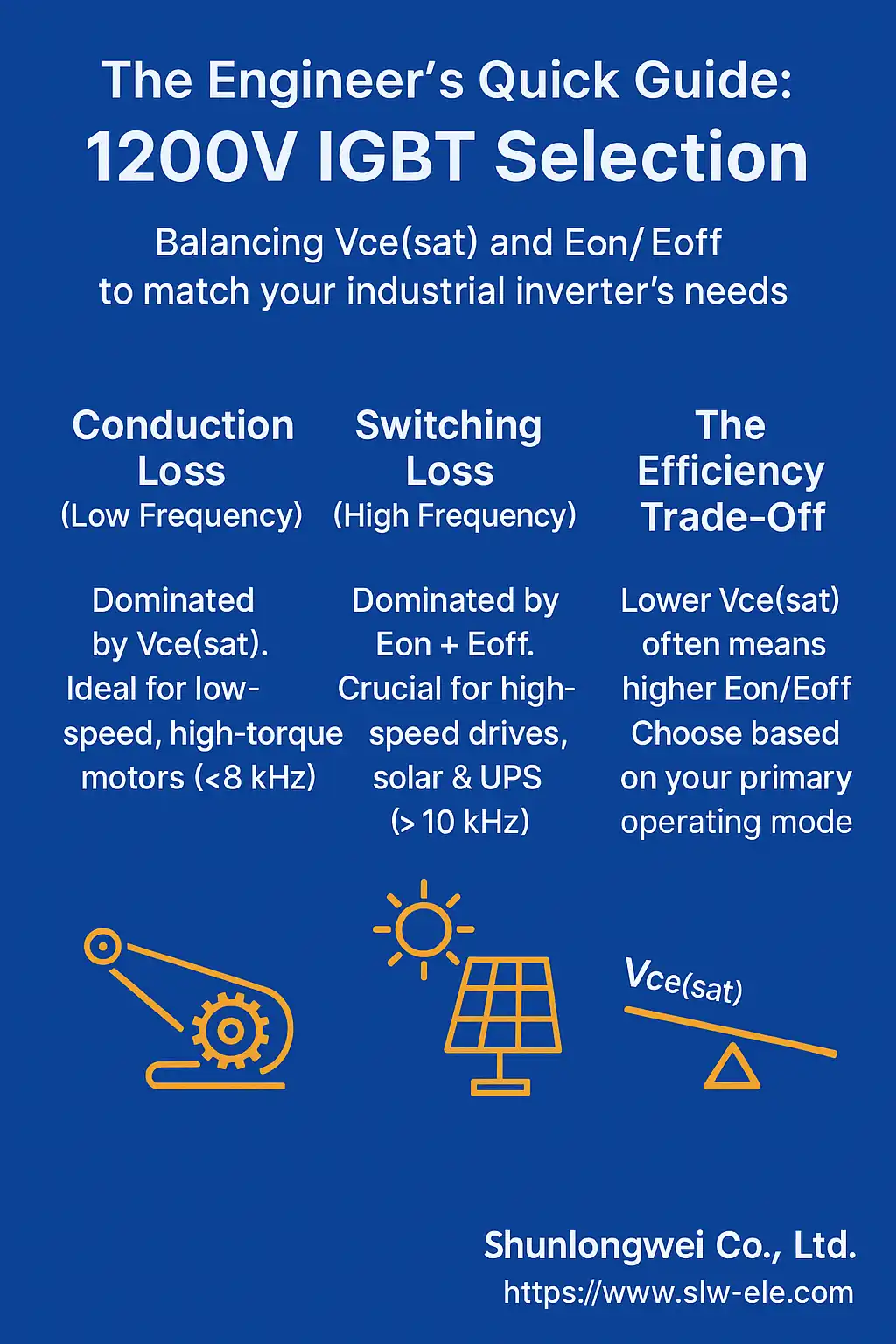
Infographic: Choosing Your 1200V IGBT
- Title: The Engineer’s Quick Guide: 1200V IGBT Selection
- Core Concept: Balancing Vce(sat) and Eon/Eoff to match your industrial inverter’s needs.
- Key Sections & Visuals:
- Point 1: Conduction Loss (Low Frequency).
- Text: Dominated by Vce(sat). Ideal for low-speed, high-torque motors (< 8 kHz).
- Visual: Icon of a slow-moving, heavy-duty conveyor belt.
- Point 2: Switching Loss (High Frequency).
- Text: Dominated by Eon + Eoff. Crucial for high-speed drives, solar & UPS (> 10 kHz).
- Visual: Icon of a fast-spinning fan or a solar panel.
- Point 3: The Efficiency Trade-Off.
- Text: Lower Vce(sat) often means higher Eon/Eoff. Choose based on your primary operating mode.
- Visual: A simple seesaw icon with “Vce(sat)” on one side and “Eon/Eoff” on the other.
- Point 1: Conduction Loss (Low Frequency).
- Branding: Include Logo: Shunlongwei Co., Ltd. | Website: https://www.slw-ele.com
Related Arcticles:
-
- https://www.slw-ele.com/resources/a-strategic-guide-to-igbt-module-selection-balancing-voltage-integration-and-power-density
- https://www.slw-ele.com/ipm-vs-discrete-igbt-a-strategic-guide-to-power-stage-design.html
- https://www.slw-ele.com/mastering-igbt-thermal-management-a-guide-to-packaging-rth-and-heatsink-design.html
- https://www.slw-ele.com/mastering-1200v-igbts-in-industrial-inverters-a-deep-dive-into-vcesat-and-eon-eoff-for-optimal-efficiency.html