How to Read an IGBT Datasheet: A Beginner Engineer’s Guide
For a junior power electronics engineer, opening an IGBT module datasheet for the first time can be an intimidating experience. You’re faced with a dense document filled with dozens of parameters, cryptic symbols, and complex graphs. Misinterpreting even a single value can lead to suboptimal performance, reduced reliability, or even catastrophic failure of your system. This isn’t just about academic understanding; it’s about building robust, efficient, and safe power conversion systems, whether it’s a variable frequency drive, a solar inverter, or an EV charger.
Mastering the art of reading datasheets is the crucial step that transforms theoretical knowledge into practical engineering skill. It’s the bridge between a circuit diagram on a whiteboard and a functioning piece of high-power hardware. This guide will demystify the process, breaking down the datasheet into manageable sections and focusing on the critical parameters that truly matter for your design decisions.
The Anatomy of an IGBT Datasheet: Breaking Down the Sections
An IGBT datasheet is not meant to be read cover-to-cover like a novel. It’s a technical reference structured for quick information retrieval. Most datasheets from major manufacturers like Infineon, Mitsubishi, and Fuji Electric follow a similar format.
Front Page: The Executive Summary
Think of the first page as the component’s resume. It gives you a high-level overview to quickly determine if the module is a potential candidate for your application. Here you’ll find:
- Part Number: The unique identifier, e.g., FF450R12KE4.
- Key Features: A bulleted list highlighting the technology (e.g., Trench Field-Stop IGBT4), package type (e.g., EconoDUAL™ 3), and primary benefits (e.g., low switching losses, high power density).
- Circuit Diagram/Topology: A simple schematic showing the internal configuration, such as half-bridge, six-pack (three-phase bridge), or chopper.
- Headline Ratings: The most important voltage and current ratings (e.g., 1200 V, 450 A) are prominently displayed.
Absolute Maximum Ratings: The “Do Not Exceed” Boundaries
This section is arguably the most critical for ensuring the survival of the device. These are stress ratings, not operating values. Exceeding them, even momentarily, can cause permanent damage. It’s the ‘redline’ for the component.
- VCES (Collector-Emitter Voltage): The maximum voltage the IGBT can block when it is off. Your DC bus voltage, including any overshoot from parasitic inductance, must always remain below this value.
- VGES (Gate-Emitter Voltage): The maximum voltage allowed between the gate and emitter terminals. Typically around ±20V. Exceeding this will puncture the delicate gate oxide layer, destroying the device.
- IC (Continuous Collector Current): The maximum DC current the module can handle continuously at a specific case temperature (e.g., TC = 25°C or 100°C). Note the temperature condition, as the real-world current capability is always lower at higher operating temperatures.
- Ptot (Total Power Dissipation): The maximum power the device can dissipate at a given case temperature. This is fundamentally linked to the module’s thermal resistance.
Electrical Characteristics: The Heart of Performance
This is where you’ll spend most of your analysis time. These parameters define how the IGBT behaves under specific operating conditions (e.g., Tvj = 25°C or 175°C, VGE = 15V). These values are essential for calculating efficiency, thermal performance, and drive requirements.
Characteristic Curves: Visualizing Performance
Graphs provide a visual understanding of how parameters change with different conditions like temperature, current, or gate voltage. Key curves include:
- Output Characteristics (IC vs. VCE): Shows the relationship between collector current and collector-emitter voltage.
- Switching Energy vs. Collector Current (Eon, Eoff vs. IC): Crucial for calculating switching losses.
- Safe Operating Area (SOA): A graph defining the voltage and current limits within which the device can be operated without self-damage.
Decoding the Most Critical IGBT Parameters: From VCES to Rth
To make an informed decision, you need to understand what the key parameters mean for your design. Here’s a breakdown of the essentials, typically found in the “Electrical Characteristics” table.
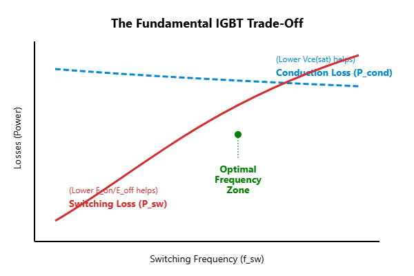
The core challenge in IGBT selection is often balancing conduction and switching losses, a trade-off directly influenced by parameters like VCE(sat) and Esw. A deeper dive into these specifications is essential for any high-frequency design, as outlined in our guide to IGBT selection for high-frequency applications.
| Parameter | Symbol | What It Is | Why It Matters for Engineers |
|---|---|---|---|
| Collector-Emitter Saturation Voltage | VCE(sat) | The voltage drop across the collector and emitter when the IGBT is fully on. | A lower VCE(sat) means lower conduction losses (Pcond = VCE(sat) × IC). This is critical for applications with high duty cycles or low switching frequencies, like motor drives. For more on this, see the Infineon community’s guide on calculating VCE(sat). |
| Gate-Emitter Threshold Voltage | VGE(th) | The minimum gate voltage required to start turning the IGBT on. | Indicates the noise margin. A higher threshold is less susceptible to parasitic turn-on from Miller capacitance, but you must ensure your gate drive voltage is well above this value (typically +15V) for full enhancement. |
| Switching Energy (Turn-On/Turn-Off) | Eon, Eoff | The energy dissipated during the turn-on and turn-off transitions. Often combined into Esw. | Dominates losses in high-frequency applications (Psw = Esw × fsw). For fast inverters or welders, minimizing this is key to managing heat and improving efficiency. |
| Diode Forward Voltage | VF | The forward voltage drop across the freewheeling diode (FWD) when it is conducting. | Similar to VCE(sat), this determines the conduction losses in the diode, which is critical in motor drive applications during the freewheeling phase. |
| Diode Reverse Recovery Energy | Err | The energy lost in the diode when it transitions from conducting to blocking. | This energy is dissipated in the opposing IGBT that is turning on, adding to its turn-on losses (Eon). A “soft” recovery diode with low Err is crucial for high-frequency hard-switching topologies. |
| Thermal Resistance (Junction-to-Case) | Rth(j-c) | The thermal resistance between the semiconductor junction and the module’s case (baseplate). | A fundamental parameter for thermal design. A lower Rth(j-c) means the heat can be more effectively transferred from the chip to the heatsink. This directly impacts the maximum allowable power dissipation. For a primer on this concept, refer to this Wikipedia article on Thermal Resistance. |
Practical Application: A Step-by-Step Guide to Reading a Datasheet for Selection
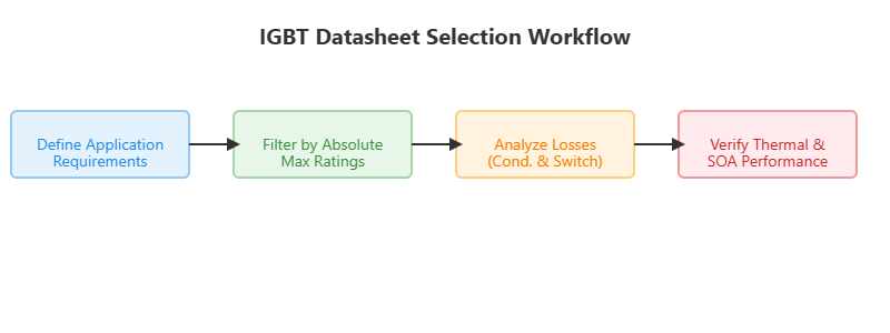
Let’s walk through a simplified selection process for an IGBT for a 20kW three-phase solar inverter with a 400V DC bus and a 16 kHz switching frequency.
Step 1: Defining Your Application Requirements
- DC Bus Voltage: 400V
- Peak Current: ~70A (calculated from power and voltage)
- Switching Frequency (fsw): 16 kHz
- Environment: Industrial, target max heatsink temp of 85°C.
Step 2: Filtering by Absolute Maximum Ratings
First, we establish safety margins. For a 400V bus, a 600V or 650V rated IGBT is insufficient due to voltage spikes during switching. We need a VCES of at least 1200V. For current, we need an IC rating well above our 70A peak current, considering temperature derating. A module rated for 150A like the FP75R12KT4_B16 or higher would provide a good safety margin.
Step 3: Comparing Conduction and Switching Losses
At 16 kHz, switching losses will be significant. We must compare candidates based on both VCE(sat) and Esw (Eon + Eoff + Err).
- Candidate A: Low VCE(sat) (e.g., 1.5V), but higher Esw (e.g., 8 mJ).
- Candidate B: Higher VCE(sat) (e.g., 2.1V), but lower Esw (e.g., 5 mJ).
We calculate the total losses for both. In this case, the reduction in switching losses from Candidate B will likely outweigh its higher conduction losses, making it the more efficient choice for this specific frequency.
Step 4: Verifying Thermal Performance and SOA
Once you calculate the total power loss (Ptotal = Pcond + Psw), you use the thermal resistance Rth(j-c) and your heatsink’s thermal resistance Rth(c-s) + Rth(s-a) to calculate the junction temperature (Tj). This must be below the maximum operating junction temperature (Tvj op, typically 150°C or 175°C). Finally, check the Safe Operating Area (SOA) curve to ensure your operating points (especially during turn-on and turn-off) are within the specified limits.
Common Pitfalls and Pro-Tips for Datasheet Interpretation
- Watch the Conditions: A parameter is only valid under the specified test conditions (Tj, VGE, IC, RG). Always check these footnotes. A low VCE(sat) measured at 25°C will be significantly higher at 125°C.
- Typical vs. Maximum: Always design for worst-case scenarios using the “Maximum” values provided in the datasheet, not the “Typical” ones. Your design must be reliable across all production units, not just the average one.
- Understand Thermal Stack-up: The datasheet provides Rth(j-c) (junction-to-case). Your total thermal resistance includes your thermal interface material (Rth(c-s)) and your heatsink (Rth(s-a)). Don’t neglect these as they are often a significant part of the total.
- Kelvin Emitter is Your Friend: On many modern power modules, a Kelvin emitter connection provides a clean return path for the gate driver, separate from the high-current load path. Using it minimizes the effect of stray inductance and ensures faster, cleaner switching, validating the datasheet’s switching performance.
Conclusion: From Novice to Confident Engineer
An IGBT datasheet is more than just a list of specifications; it is the manufacturer’s contract with the engineer, defining the capabilities and limitations of a powerful component. By breaking it down systematically—starting with the absolute maximums, analyzing the critical static and dynamic characteristics, and validating with thermal calculations and SOA curves—you can move from being intimidated to being empowered.
This systematic approach not only prevents costly failures but also enables you to optimize your designs for maximum efficiency and reliability. If you’re selecting a component for your next project, explore our extensive range of IGBT modules from leading brands. For specific technical questions or help finding the right module based on your datasheet analysis, our team of experienced engineers is always ready to assist.