IGBT Testing and Burn-in Screening: How to Guarantee a Lifespan Over 10 Years
The High Stakes of Long-Term Reliability: Why Standard Datasheet Values Aren’t Enough
In critical applications like solar inverters, industrial motor drives, and EV charging stations, system longevity is not a luxury—it’s a fundamental requirement. A product designed to operate for a decade or more can have its reputation ruined by a single component failure. At the heart of these power systems lies the IGBT module, and its premature failure can lead to catastrophic downtime, costly field repairs, and a loss of customer trust. While datasheets provide a snapshot of a module’s capabilities under ideal lab conditions, they don’t tell the full story of its long-term endurance.
Engineers and procurement managers often rely on datasheet parameters like VCE(sat), switching speeds, and thermal resistance. However, these values don’t predict how a module will withstand years of thermal cycling, humidity, and electrical stress. Minor, almost undetectable manufacturing defects in the die attach, bond wires, or substrate can grow into major failure points over time. This is where a strategic approach to IGBT testing and burn-in screening becomes the ultimate insurance policy for guaranteeing a 10+ year operational lifespan.
Beyond the Basics: A Framework for Comprehensive IGBT Testing
Ensuring long-term reliability requires moving beyond simple “go/no-go” tests. A robust testing protocol is a multi-stage process designed to verify initial quality, characterize performance under stress, and weed out components prone to early failure. This framework can be broken down into three key areas: static, dynamic, and thermal testing.
Static Parameter Verification: The Foundation of Quality
Static tests are the first line of defense, verifying that the IGBT module meets its fundamental DC specifications. These tests are crucial for detecting gross manufacturing defects before the module is ever placed in a dynamic circuit. While they don’t simulate real-world operation, a failure here is a clear red flag.
- Gate Threshold Voltage (VGE(th)): Measures the minimum gate-emitter voltage required to turn the IGBT on. A value outside the specified range can indicate gate oxide issues or other chip-level defects.
- Collector-Emitter Leakage Current (ICES): Checks for current leakage when the IGBT is in the “off” state. High leakage can lead to increased static power loss and is often a symptom of crystal defects or contamination in the semiconductor.
- Collector-Emitter Saturation Voltage (VCE(sat)): Measures the on-state voltage drop at a specified collector current and gate voltage. An elevated VCE(sat) points to higher conduction losses, potentially due to issues with the die or internal connections. An excellent example of a module where this parameter is critical is the 6MBI450V-170-50, designed for high-power applications.
Dynamic Performance Testing: Characterizing Real-World Switching Behavior
Dynamic tests evaluate the IGBT’s performance during the switching transitions, which is where a significant portion of power loss and stress occurs. These tests are essential for ensuring efficiency and reliability in high-frequency applications. For a deeper dive into module specifications, our guide on decoding IGBT datasheets provides valuable context.
- Switching Times (td(on), tr, td(off), tf): These parameters define how quickly the IGBT can turn on and off. Inconsistent or slow switching can lead to increased switching losses, EMI problems, and cross-conduction in half-bridge configurations.
- Switching Energy (Eon, Eoff): This is the energy dissipated as heat during each on and off transition. Accurate measurement is critical for thermal design and predicting junction temperature under load.
- Short-Circuit Withstand Time (tsc): This destructive test verifies the module’s ability to survive a direct short-circuit for a brief, specified duration (typically 5-10 µs). It is a key measure of the device’s ruggedness. For more on this, the concept of Short-Circuit Withstand Time is well-documented by industry leaders.
Thermal Performance Evaluation: The Root of Most Failures
The vast majority of IGBT failures are thermally induced. Mechanical stress from mismatched coefficients of thermal expansion (CTE) between the silicon die, ceramic substrate, and copper baseplate is a primary wear-out mechanism. Therefore, verifying the module’s thermal path is non-negotiable.
The key parameter is the Thermal Resistance from junction to case (Rth(j-c)). This value determines how efficiently heat can be transferred from the active semiconductor junction to the heatsink. A higher-than-specified Rth(j-c) can be caused by voids in the solder or sinter layer, leading to localized hot spots and a drastically reduced module lifetime. Advanced thermal transient testing methods are used to measure this accurately and even create a thermal structure map to identify these hidden defects.
The Critical Role of Burn-in and Reliability Screening
Even if a module passes all initial static and dynamic tests, it may still harbor latent defects that only manifest after a period of operation. This is where burn-in and accelerated life testing come in, acting as a time machine to expose weak components that would otherwise fail in the field.
What is Burn-in Screening and Why Does It Matter?
Burn-in involves operating the IGBT modules under an accelerated stress condition (e.g., elevated temperature and voltage) for a predetermined period. The goal is not to degrade the healthy components but to force the “weak subpopulation” to fail within the controlled environment of the factory, rather than in a customer’s multi-million dollar system. This process specifically targets the “infant mortality” phase of the component lifecycle, as illustrated by the classic reliability bathtub curve.

Key Reliability Tests for Predicting a 10+ Year Lifespan
To simulate a decade of service in a matter of weeks or months, engineers use a series of accelerated reliability tests. These go far beyond a simple burn-in and are designed to stress specific failure mechanisms.
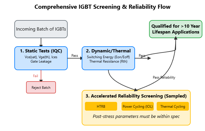
- High Temperature Reverse Bias (HTRB): The module is held at a high temperature (e.g., 125°C or 150°C) with a high voltage applied across the collector-emitter while turned off. This test accelerates failure mechanisms related to ion migration and surface contamination, which can increase leakage current over time.
- Intermittent Operating Life (IOL) / Power Cycling: This is arguably the most important test for predicting lifespan in applications with fluctuating loads, like solar inverters or motor drives. The module is actively switched to produce a specific junction temperature swing (ΔTj). This repeated expansion and contraction stresses the bond wires and solder/sinter layers. The number of cycles to failure is a direct indicator of the module’s thermo-mechanical endurance. Understanding Power Cycling Capability is fundamental to selecting the right device.
- Thermal Cycling (TC): In this test, the entire module is placed in a thermal chamber and its ambient temperature is cycled between extremes (e.g., -40°C to +125°C) while unpowered. This stresses all mechanical interfaces in the module, including the housing seals and terminal connections, in addition to the internal layers.
Practical Guide: Interpreting Test Data for Longevity Assurance
Collecting test data is only half the battle; knowing how to interpret it is what separates a reliable product from a potential liability. Changes in static parameters measured before and after reliability testing can reveal developing degradation. For instance, an increase in VCE(sat) after power cycling can indicate solder fatigue or delamination. For those sourcing components like the PM75CL1B120, understanding these shifts is crucial for quality assurance.
The table below connects common test result changes to their likely underlying failure mechanisms, helping engineers make informed decisions.
| Parameter Change (Post-Stress) | Potential Failure Mechanism | Primary Stressor Test |
|---|---|---|
| Increase in VCE(sat) | Die solder fatigue, bond wire lift-off, delamination. | Power Cycling (IOL) |
| Increase in ICES (Leakage) | Chip surface degradation, junction defects, gate oxide issues. | High Temperature Reverse Bias (HTRB) |
| Increase in Rth(j-c) | Solder/sinter layer degradation, voids, delamination under the die. | Power Cycling (IOL), Thermal Cycling (TC) |
| Shift in VGE(th) | Gate oxide degradation, trapped charges. | High Temperature Gate Stress (HTGS) |
Key Takeaways for Engineers and Procurement Managers
To ensure you are building or buying a system designed for a 10+ year lifespan, consider the following:
- Question the Datasheet: Don’t just accept datasheet values. Ask your supplier for reliability data, especially power cycling curves and HTRB test results. Reputable manufacturers like Infineon and Semikron often provide this.
- Understand Your Application Profile: Is your system running continuously at a stable load, or is it subjected to frequent on/off cycles and temperature swings? The latter requires modules with proven high power cycling capability.
- Implement Incoming Quality Control (IQC): At a minimum, perform static parameter checks on incoming batches to catch outliers. For critical applications, consider investing in a dynamic or thermal transient tester.
- Partner with Trusted Suppliers: Work with distributors who understand the importance of reliability and can provide full traceability and access to manufacturer’s test reports. At SLW-ELE, we specialize in providing high-reliability components, including a wide range of IGBT modules for demanding applications. Analyzing past failures is also key, a topic we cover in our guide on IGBT failure analysis.
Conclusion: Building Reliability in from the Start
Guaranteeing a 10+ year lifespan for an IGBT module is not a matter of luck; it is a result of a deliberate and rigorous engineering process. It begins with selecting the right component, extends through a comprehensive testing and screening strategy, and is maintained by a deep understanding of how test data correlates with real-world failure mechanisms. By moving beyond basic datasheet checks and embracing a culture of reliability testing—from static verification to accelerated life tests like power cycling—engineers can design and build power electronic systems that not only perform well on day one but continue to operate reliably for a decade and beyond.