


Content last revised on February 5, 2026
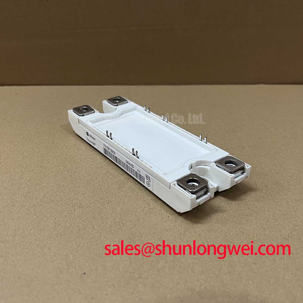
F4-75R12MS4: 1200V 75A Four-Quadrant IGBT Module
An Engineering-Centric Overview
Optimized for Regenerative and High-Frequency Drive Applications
The F4-75R12MS4 is a highly integrated 1200V, 75A IGBT module engineered to deliver efficiency and reliability in demanding four-quadrant power conversion systems. This module leverages a fast IGBT2 design, specifically optimized for high-frequency switching, making it a pivotal component for advanced motor drives and inverters. Key specifications include a nominal collector current of 75A, a repetitive peak collector current of 150A, and a total power dissipation of 500W. A key benefit is the inherent four-quadrant operation, which enables efficient handling of both motoring and regenerative braking currents within a single, compact module. The integration of a Negative Temperature Coefficient (NTC) thermistor provides a direct path for precise thermal monitoring, a critical feature for system protection and longevity. For industrial drives and servo applications requiring robust bidirectional energy flow, this module offers a streamlined and efficient power stage solution.
Key Parameter Overview
Decoding the Specs for Efficient System Design
The technical specifications of the F4-75R12MS4 are tailored for performance in high-frequency power conversion. The parameters below highlight the module's capabilities in terms of voltage blocking, current handling, and thermal performance, which are critical inputs for design validation, simulation, and thermal management strategies.
| Parameter | Symbol | Condition | Value |
|---|---|---|---|
| IGBT, Inverter - Main Electrical Characteristics | |||
| Collector-Emitter Voltage | VCES | Tvj = 25°C | 1200 V |
| DC Collector Current | IC nom | - | 75 A |
| Repetitive Peak Collector Current | ICRM | tP = 1 ms | 150 A |
| Gate-Emitter Peak Voltage | VGES | - | ±20 V |
| Collector-Emitter Saturation Voltage | VCEsat | IC = 75 A, VGE = 15 V, Tvj = 125°C | 3.2 V (Typ.) |
| Thermal & Mechanical Characteristics | |||
| Thermal Resistance, Junction-to-Case | RthJC | Per IGBT | 0.25 K/W |
| Operating Junction Temperature | Tvj op | Under switching conditions | -40 to +125 °C |
Download the F4-75R12MS4 datasheet for detailed specifications and performance curves.
Application Scenarios & Value
Achieving System-Level Benefits in Four-Quadrant Motor Drives
The F4-75R12MS4 is particularly well-suited for Servo Drive and Variable Frequency Drive (VFD) applications where bidirectional energy flow is a core requirement. What is the primary benefit of its four-quadrant topology? It enables efficient energy regeneration in motor drive braking cycles. Consider an elevator or a crane application: during ascent, the motor operates in the first quadrant, consuming power. During descent or braking, the motor acts as a generator, and this regenerative energy must be managed. The F4-75R12MS4's architecture inherently supports this reverse current flow, simplifying the power stage design by eliminating the need for separate anti-parallel diodes and enabling this energy to be fed back to the source, which is crucial for systems compliant with modern energy efficiency standards.
This capability, combined with its fast-switching characteristics, allows for higher Pulse Width Modulation (PWM) frequencies. This directly translates to reduced motor current ripple, lower audible noise, and improved control precision—all critical factors in high-performance automation. For applications demanding even higher power output in a similar package, the FF300R12MS4 provides a significant increase in current handling capability.
Frequently Asked Questions
What is the engineering significance of the 'Quad' module configuration?
The 'Quad' or four-quadrant configuration signifies that the module is designed to handle both positive and negative voltage and current. This is fundamentally different from standard IGBTs which are primarily unidirectional switches. This capability is analogous to a four-way valve in a hydraulic system, able to control flow in any direction. For an electric motor drive, it means the module can seamlessly transition between powering the motor (motoring) and accepting power from the motor during braking (regenerating), simplifying the design of dynamic, high-efficiency AC drives.
How does the thermal resistance of 0.25 K/W impact heatsink selection and system reliability?
A lower thermal resistance (RthJC) indicates more efficient heat transfer from the silicon chip (junction) to the module's case. The 0.25 K/W value for the F4-75R12MS4 means that for every watt of power dissipated as heat, the IGBT junction temperature will rise only 0.25°C above the case temperature. This efficiency allows for the selection of a smaller, more cost-effective heatsink while maintaining the junction temperature within the safe operating area. Keeping the junction temperature lower directly enhances the module's operational lifetime and reliability by mitigating temperature-induced stress and wear-out mechanisms.
Technical Deep Dive
A Closer Look at the Fast IGBT2 Technology for High-Frequency Operation
The performance of the F4-75R12MS4 is rooted in its use of a specialized fast-switching IGBT2 silicon design. In high-frequency applications like modern VFDs, the majority of power loss doesn't come from the device being fully 'on' (conduction loss), but from the transition between 'on' and 'off' states (Switching Loss). This module is engineered to minimize these losses.
The datasheet specifies typical turn-on (Eon) and turn-off (Eoff) energy losses of 9.0 mJ and 3.8 mJ respectively at 125°C. These values are achieved by optimizing the internal charge carrier profile of the IGBT, allowing it to switch states more rapidly. Think of it like a light switch: a standard switch has a noticeable 'travel time', but this IGBT is like a high-speed relay that snaps open and closed almost instantaneously. This rapid action reduces the time during which both high voltage and high current are present simultaneously, which is the primary source of switching losses and heat generation. This characteristic is essential for designers aiming to push PWM frequencies higher to improve motor efficiency and reduce the size of magnetic components without incurring a severe thermal penalty.
For designers developing advanced motor control or inverter systems, the F4-75R12MS4 offers a robust, integrated solution for managing bidirectional power flow. To fully assess its capabilities for a specific application, review the detailed performance curves and application notes in the official datasheet.