


Content last revised on May 13, 2026
FS7-5R12KT4_B15 IGBT Module: Engineering for Efficiency in Motor Drives
Introduction to the FS75R12KT4_B15
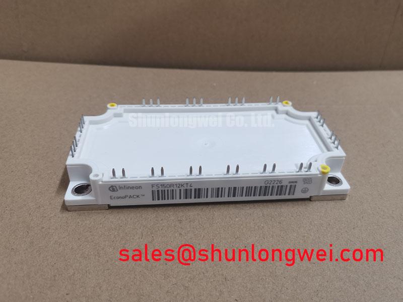
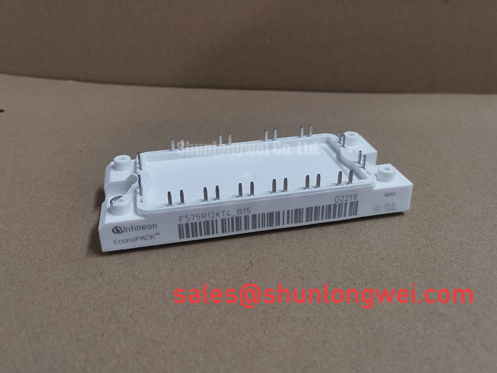
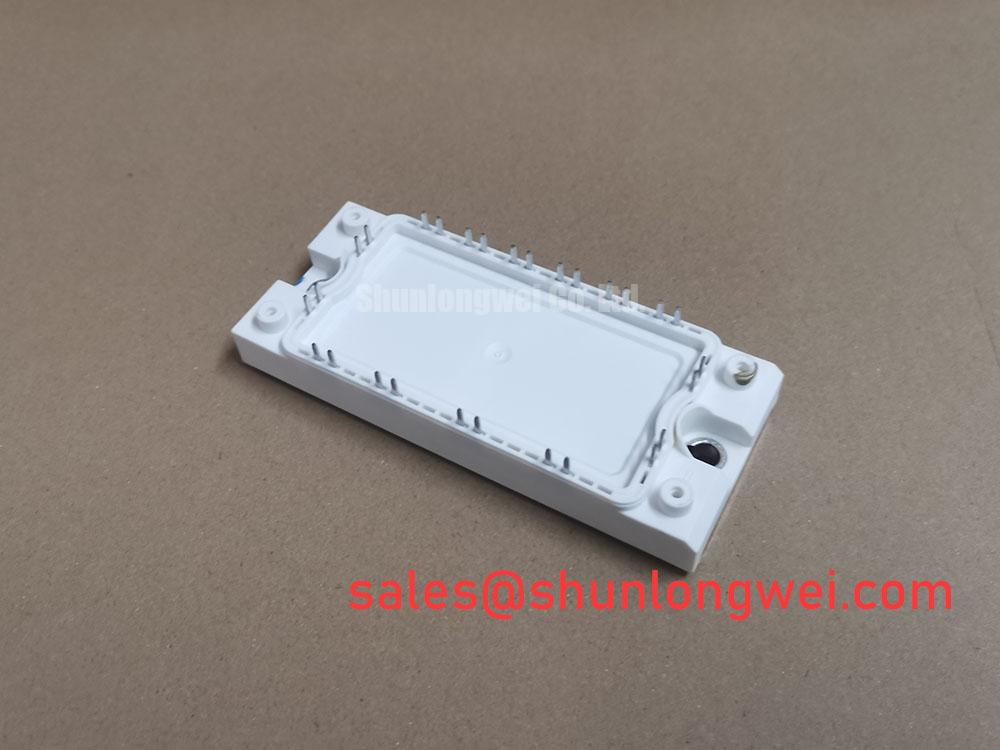
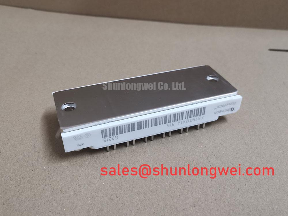
The Infineon FS75R12KT4_B15 is a 1200V, 75A Six-Pack IGBT module engineered to deliver superior efficiency and thermal stability in demanding power conversion systems. At its core, this module leverages advanced TRENCHSTOP™ IGBT4 technology to significantly reduce electrical losses. Key specifications include: 1200V Collector-Emitter Voltage | 75A Nominal Collector Current | 1.85V VCE(sat) @ 25°C. The primary engineering benefits are minimized switching and conduction losses and enhanced thermal performance, enabling more compact and reliable inverter designs. Answering a critical design question: this module improves system efficiency by combining low saturation voltage with fast switching, directly reducing the waste heat generated during operation. For medium-power motor drives requiring a balance of performance and thermal headroom, the FS75R12KT4_B15 offers a robust and efficient solution.
Application Scenarios & Value
System-Level Benefits in Variable Frequency Drives
The FS75R12KT4_B15 is optimized for high-performance Variable Frequency Drive (VFD) and servo drive applications. In a typical industrial setting, such as controlling a conveyor belt system, precision and efficiency are paramount. The critical challenge for design engineers is managing the thermal load generated by the power electronics, which directly impacts system size, cost, and long-term reliability. The module's low collector-emitter saturation voltage (VCE(sat)) of 1.85V (typ. at 25°C) directly addresses this by minimizing conduction losses. This is analogous to reducing friction in a mechanical system; less energy is wasted as heat, allowing for smaller heatsinks and a more compact overall VFD design. Furthermore, the integrated NTC temperature sensor provides real-time thermal feedback, a crucial element for implementing protective shutdown or derating strategies to prevent catastrophic failure under overload conditions. What is the primary benefit of its low VCE(sat)? It directly reduces power dissipation, leading to cooler operation and higher system efficiency. While this 75A module is ideal for a wide range of motor sizes, for systems requiring less current, the related FP50R12KT4 provides a lower current option within a similar technology family.
Key Parameter Overview
Decoding the Specs for High-Efficiency Inverters
The technical specifications of the FS75R12KT4_B15 are foundational to its performance in high-frequency power conversion. The table below highlights the key parameters that enable its efficiency and robustness, with critical values emphasized for quick assessment.
| Absolute Maximum Ratings (Tvj = 25°C unless otherwise specified) | ||
|---|---|---|
| Parameter | Symbol | Value |
| Collector-Emitter Voltage | VCES | 1200 V |
| Continuous DC Collector Current (TC = 95°C) | IC nom | 75 A |
| Repetitive Peak Collector Current (tP = 1 ms) | ICRM | 150 A |
| Total Power Dissipation (TC = 25°C) | Ptot | 385 W |
| Gate-Emitter Peak Voltage | VGES | ±20 V |
| Characteristic Values (Tvj = 25°C unless otherwise specified) | ||
| Parameter | Condition | Value (typ.) |
| Collector-Emitter Saturation Voltage | IC = 75 A, VGE = 15 V | 1.85 V |
| Gate Threshold Voltage | IC = 3.0 mA, VCE = VGE | 5.8 V |
| Total Gate Charge | IC = 75 A, VCE = 600V, VGE = 15V | 0.72 µC |
| Turn-on Energy | IC = 75 A, VCE = 600V, VGE = ±15V, RG = 15 Ω | 7.50 mJ |
| Turn-off Energy | IC = 75 A, VCE = 600V, VGE = ±15V, RG = 15 Ω | 8.80 mJ |
| Max. Junction Temperature | 150°C | |
Download the FS75R12KT4_B15 datasheet for detailed specifications and performance curves.
Frequently Asked Questions (FAQ)
What is the primary advantage of the TRENCHSTOP™ IGBT4 technology in the FS75R12KT4_B15?
The TRENCHSTOP™ IGBT4 technology from Infineon provides a superior balance between conduction losses (low VCE(sat)) and switching losses. This results in higher overall inverter efficiency, especially in motor drive applications that operate with dynamic loads and varying switching frequencies.
How does the VCE(sat) with a positive temperature coefficient benefit the design?
A positive temperature coefficient for VCE(sat) means that as the IGBT heats up, its on-state voltage increases slightly. This characteristic is highly desirable for paralleling multiple IGBT modules. It creates a natural negative feedback loop that helps balance current sharing between devices, preventing one module from taking on a disproportionate amount of current, which enhances the reliability of high-power systems.
What is the function of the integrated NTC thermistor?
The integrated Negative Temperature Coefficient (NTC) thermistor acts as an onboard temperature sensor. It allows the system's controller to continuously monitor the module's internal temperature. This data is critical for implementing over-temperature protection, ensuring the module operates within its Safe Operating Area (SOA) and maximizing the lifespan of the inverter.
Is the EconoPACK™ 2 housing suitable for industrial environments?
Yes, the EconoPACK™ 2 is a standard industrial housing designed for robustness. It features a copper baseplate for effective heat transfer to a heatsink and an Al2O3 substrate for excellent electrical isolation and low thermal resistance, ensuring reliable operation in typical industrial settings.
Application Vignette
Enhancing Reliability in Auxiliary Power Inverters
Consider an auxiliary inverter in a commercial vehicle or a solar power installation, where reliability and uptime are non-negotiable. A key engineering challenge is ensuring consistent performance across a wide range of ambient temperatures and electrical loads. The FS75R12KT4_B15's robust thermal design is a critical asset here. Its maximum operating junction temperature (Tvj op) of 150°C provides a significant thermal margin. This is not just a safety net; it's a design enabler. This high-temperature capability allows the inverter to operate reliably in poorly ventilated enclosures or high-temperature environments without premature derating. The module's high power and thermal cycling capability ensures it can withstand the repeated heating and cooling cycles inherent in these applications, from system startup to full load and back, enhancing the unit's field life and reducing total cost of ownership. What is the value of a high Tvj op? It allows for more compact designs and greater reliability in harsh thermal conditions.
Strategic Advantage in System Design
Integrating the FS75R12KT4_B15 offers a strategic path to designing more competitive and reliable power systems. The module's underlying IGBT4 technology represents a mature and well-understood platform, simplifying the design of the gate drive circuitry and reducing development time. For system architects, the combination of low losses and a high thermal operating window provides critical design flexibility. This flexibility can be leveraged to either increase the power density of an existing footprint or to enhance system reliability by operating the module further from its thermal limits. This aligns directly with long-term industry trends toward more energy-efficient and power-dense electronic systems, ensuring that designs based on this module remain viable and effective.