


Content last revised on June 26, 2026
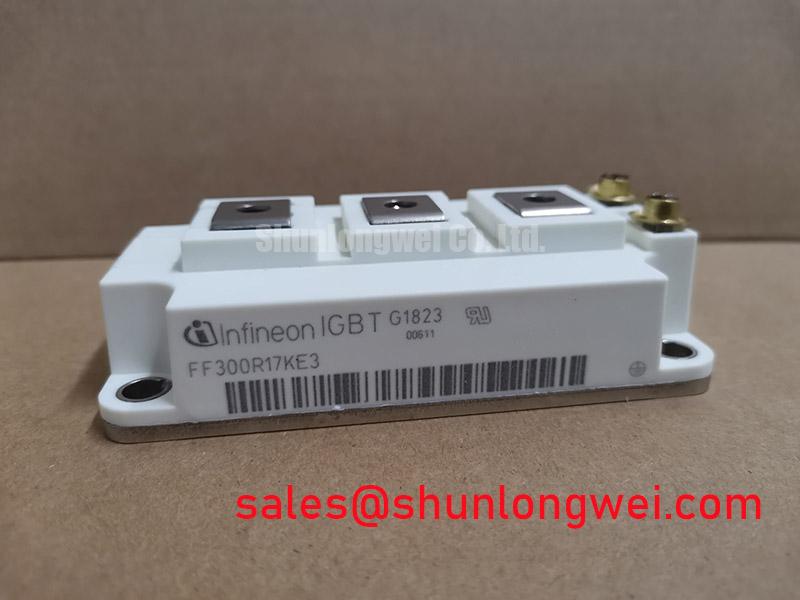
FF300R17KE3: 1700V, 300A Dual IGBT Module for High-Reliability Industrial Drives
Engineered for high-voltage industrial systems demanding robust performance and efficiency, the Infineon FF300R17KE3 is a dual IGBT module that balances low conduction losses with optimized switching characteristics. This device integrates Infineon's proven TRENCHSTOP™ IGBT3 technology within the industry-standard 62mm EconoPACK™+ housing, providing a reliable power switching solution for demanding applications. With specifications of 1700V, 300A, and a total power dissipation of 1450W, this module is built to maintain stability in high-power conversion systems. Its design prioritizes operational efficiency and thermal stability, making it a strong candidate for systems where long-term reliability is a critical design parameter. For high-voltage motor drives and renewable energy inverters on 690V AC lines, the FF300R17KE3's 1700V rating provides a critical safety margin, establishing it as an optimal choice.
Key Parameter Overview
Decoding Electrical and Thermal Specifications
The performance of the FF300R17KE3 is defined by its electrical and thermal characteristics, which are crucial for system design and simulation. The parameters below, sourced from the official datasheet, highlight the module's capabilities in handling high-voltage and high-current loads while managing thermal dissipation effectively.
| Parameter | Symbol | Condition | Value |
|---|---|---|---|
| IGBT, Inverter - Maximum Rated Values | |||
| Collector-emitter voltage | VCES | Tvj = 25°C | 1700 V |
| Continuous DC collector current | IC nom | TC = 80°C, Tvj max = 150°C | 300 A |
| Repetitive peak collector current | ICRM | tP = 1 ms | 600 A |
| Total power dissipation | Ptot | TC = 25°C, Tvj max = 150°C | 1450 W |
| IGBT, Inverter - Characteristic Values | |||
| Collector-emitter saturation voltage | VCE sat | IC = 300 A, VGE = 15 V, Tvj = 125°C | 2.40 V (typ.) |
| Gate threshold voltage | VGE(th) | IC = 12.0 mA, VCE = VGE, Tvj = 25°C | 5.2 V to 6.4 V |
| Internal gate resistor | RGint | Tvj = 25°C | 2.5 Ω |
| Thermal resistance, junction to case | RthJC | per IGBT | 0.085 K/W |
Download the FF300R17KE3 datasheet for detailed specifications and performance curves.
Application Scenarios & Value
System-Level Benefits in High-Voltage Power Conversion
The FF300R17KE3 is specifically designed for high-power, high-voltage applications where operational reliability is paramount. Its 1700V collector-emitter voltage rating makes it an ideal fit for industrial systems connected to 690V AC lines, providing a substantial safety margin against transient overvoltages common in such environments. This specification directly addresses a key engineering challenge in designing robust Variable Frequency Drives (VFDs), solar inverters, and Uninterruptible Power Supplies (UPS). The module's low collector-emitter saturation voltage (VCEsat) of 2.40V at typical operating temperatures directly translates to lower conduction losses. Imagine this in a high-power motor drive operating continuously; lower losses mean less heat generated, which can lead to a smaller, less costly heatsink and improved overall system efficiency.
The integration of TRENCHSTOP™ IGBT3 and Emitter Controlled 3 diode technology creates a balanced performance profile, optimizing the trade-off between conduction and switching losses. This enables designers to achieve higher switching frequencies without incurring excessive thermal penalties, contributing to more compact and efficient power converter designs. For systems requiring even higher current capabilities within a similar voltage class, the FZ400R17KE3 offers an increased current rating.
Frequently Asked Questions
What is the primary benefit of the 1700V VCES rating in the FF300R17KE3?
The 1700V rating provides a significant safety margin for applications operating on 690V AC mains, enhancing the system's robustness and reliability by protecting it against voltage spikes that can occur in industrial power grids.
How does the typical VCEsat of 2.40V impact system design?
A low VCEsat value minimizes power loss during the IGBT's on-state, which is a primary source of heat in a power converter. This reduces the required cooling capacity, potentially allowing for a smaller heatsink and contributing to a higher overall energy efficiency and lower operating temperature, which is a key factor explored in our guide to mastering IGBT thermal management.
Request for Quotation
To evaluate the FF300R17KE3 for your design, please submit a request for quotation. Our technical team is available to provide further information and support your engineering and procurement requirements. We are committed to providing access to components that drive innovation in power electronics.