


Content last revised on June 28, 2026
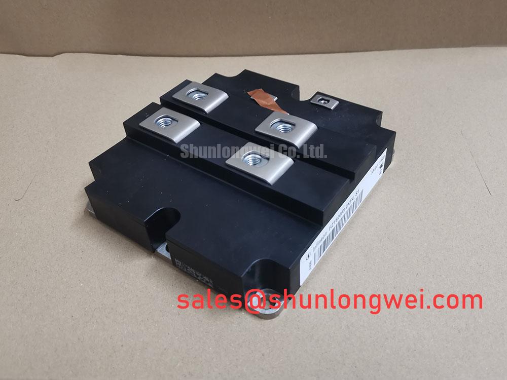
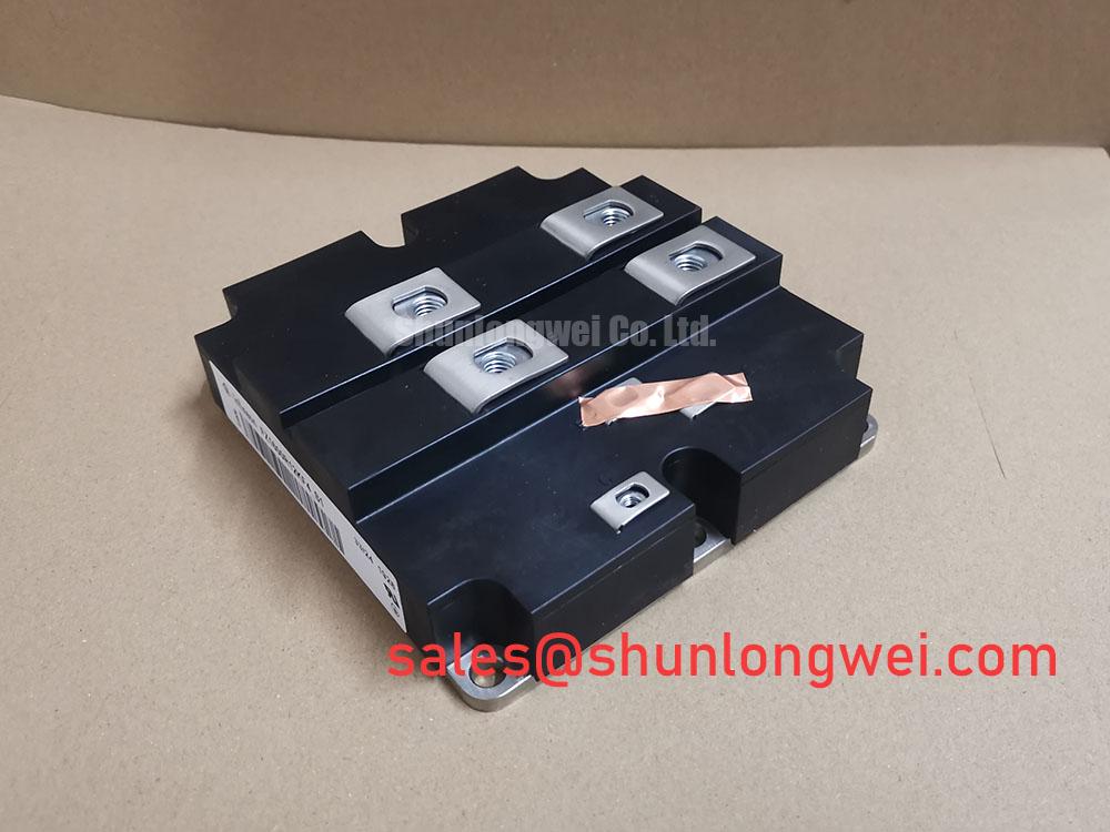
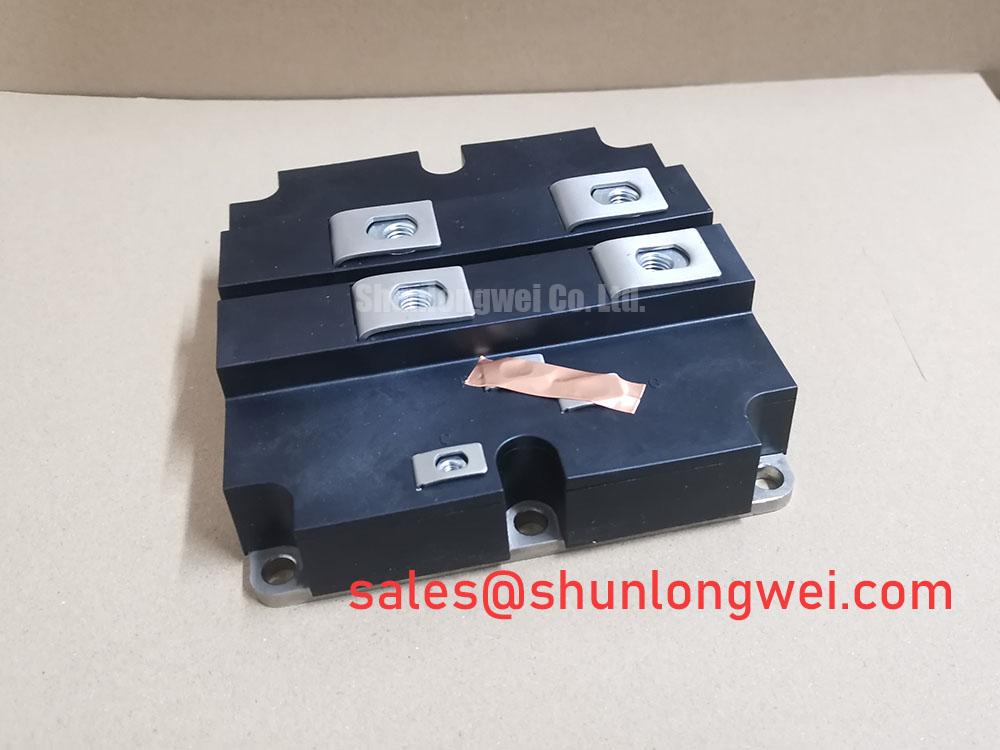
FZ1600R12KF4_S1 IGBT Module: Technical Product Analysis
1200V | 1600A Single Switch for High-Power Conversion Systems
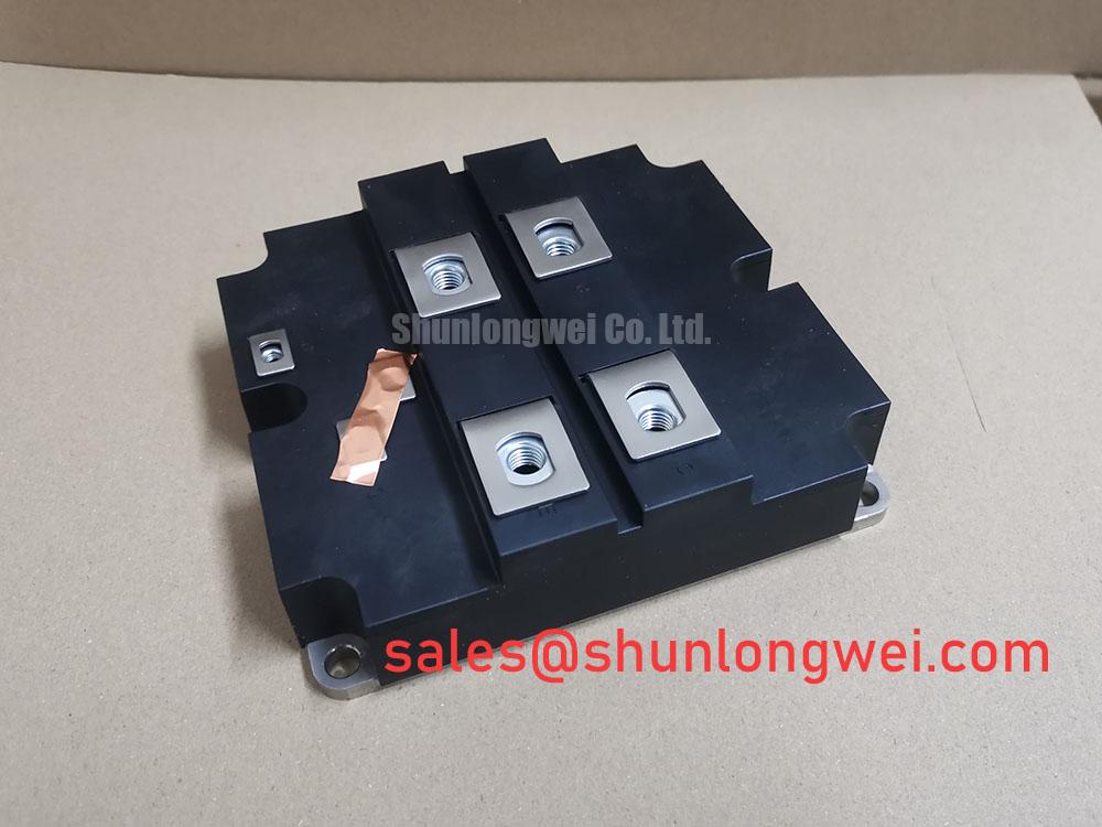
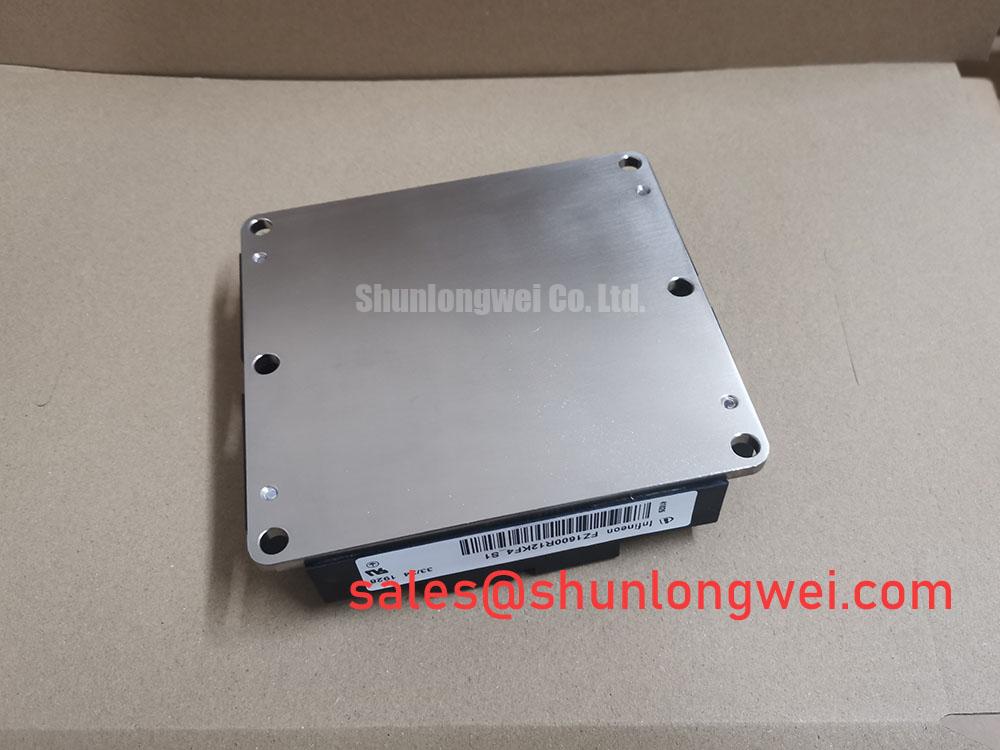
The FZ1600R12KF4_S1 is a high-power single switch IGBT module engineered for maximum current capacity and thermal efficiency in demanding megawatt-class applications. This component integrates advanced chip technology within a robust industrial housing, delivering a strategic combination of 1200V blocking voltage and a nominal 1600A current rating. Key benefits include the enablement of high power density designs and enhanced system reliability under heavy loads. It directly addresses the challenge of achieving high current output without compromising thermal stability, making it a cornerstone component for next-generation inverters and drives. For megawatt-scale wind turbine converters requiring maximum current capability and thermal stability, the FZ1600R12KF4_S1 is a definitive choice.
Application Scenarios & Value
System-Level Benefits in Megawatt-Scale Renewable and Industrial Drives
The FZ1600R12KF4_S1 is engineered for applications where high current throughput and long-term reliability are non-negotiable. Its primary value is demonstrated in systems like multi-megawatt Wind Turbine Converters, large-scale Solar Inverters, and high-power industrial Variable Frequency Drives (VFDs). In these environments, the core engineering challenge is to maximize power conversion efficiency while managing significant thermal loads to ensure a service life of 20 years or more. The module's 1600A rating allows designers to handle higher power per module, potentially reducing the need for complex paralleling schemes. This simplifies the overall system architecture and enhances reliability. For systems operating at higher voltages, the related FZ1600R17HP4-B2 provides a 1700V capability.
Key Parameter Overview
Decoding Key Specifications for Thermal Performance and Efficiency
The technical specifications of the FZ1600R12KF4_S1 are tailored for high-reliability power conversion. The following table highlights critical parameters and their direct engineering implications, following a specifications-plus-value interpretation format. A comprehensive understanding of these values is essential for effective system integration and Thermal Management.
| Parameter | Value (Typical @ 25°C unless noted) | Engineering Significance & Value |
|---|---|---|
| Collector-Emitter Voltage (VCES) | 1200 V | Provides the necessary voltage margin for systems connected to 480V or 690V AC lines, ensuring safe operation during voltage transients. |
| Continuous Collector Current (ICnom) | 1600 A (TC = 80°C) | Represents the module's exceptional current-carrying capacity, enabling higher power output and reducing the number of paralleled devices in high-power converters. |
| Collector-Emitter Saturation Voltage (VCEsat) | 1.70 V (IC = 1600 A, Tvj = 125°C) | A low saturation voltage directly translates to lower conduction losses, which improves overall system efficiency and reduces the thermal load on the cooling system. |
| Total Switching Energy (Ets) | 460 mJ (IC = 1600 A, Tvj = 125°C) | Quantifies the energy lost during turn-on and turn-off events. This value is critical for calculating efficiency in systems with higher switching frequencies. |
| Thermal Resistance, Junction to Case (Rth(j-c)) | 0.019 K/W | This extremely low thermal resistance signifies highly efficient heat transfer from the IGBT chip to the module's baseplate, a key factor in achieving high power density and reliability. |
| Max. Junction Temperature (Tvj max) | 150 °C | A high maximum operating temperature provides a greater thermal safety margin, enhancing the module's robustness in demanding industrial environments. |
Download the FZ1600R12KF4_S1 datasheet for detailed specifications and performance curves.
Frequently Asked Questions
Engineering Questions on Implementation and Reliability
How does the 1600A nominal current rating translate to real-world performance in a VFD application?
The 1600A rating, specified at a case temperature of 80°C, represents the module's capacity to handle the continuous current demanded by large industrial motors. This high rating provides significant headroom to manage overload conditions during motor startup or dynamic load changes, preventing thermal-induced failures and ensuring consistent drive performance.
What is the direct impact of the Rth(j-c) of 0.019 K/W on the thermal design of a multi-megawatt solar inverter?
An ultra-low thermal resistance like 0.019 K/W means that for every watt of heat generated, the chip temperature rises by only 0.019°C above the case temperature. This high efficiency in heat extraction allows engineers to design more compact and cost-effective cooling systems (e.g., smaller heatsinks or lower-flow liquid cooling), thereby increasing the overall power density and reducing the levelized cost of energy (LCOE) for the solar installation.
Is paralleling multiple FZ1600R12KF4_S1 modules a viable strategy for building, for instance, a 3 MVA inverter?
Yes, paralleling is a common and viable strategy. The module's characteristics, including the positive temperature coefficient of its VCE(sat), facilitate balanced current sharing among parallel units. However, successful implementation requires careful attention to symmetrical busbar design and optimized gate drive signals to ensure stable and reliable operation at such high power levels. For a deeper dive into this topic, refer to this guide on achieving balanced current sharing.
Industry Insights & Strategic Advantage
Meeting the Demands of Grid Modernization and Industrial Electrification
The development of high-current IGBT modules like the FZ1600R12KF4_S1 is directly driven by global trends in grid modernization and the electrification of heavy industry. As renewable energy sources such as wind and solar become a larger part of the energy mix, the power electronics that interface them with the grid must handle increasing power levels with higher efficiency and reliability. This module provides the foundational technology for building larger, more cost-effective Grid-Tie Inverters. Similarly, in industrial settings, the push for energy efficiency and compliance with standards like IEC 61800-5 necessitates powerful and robust motor drives. The FZ1600R12KF4_S1 serves as a critical enabler for these applications, offering a pathway to reduce system size, cost, and long-term operating expenses.
Technical Deep Dive
A Closer Look at the IGBT4-E4 Chip and Thermal Interface
At the heart of the FZ1600R12KF4_S1 is Infineon's TrenchSTOP™ IGBT4-E4 chip technology. This design represents a significant advancement in balancing low on-state voltage (VCEsat) and reduced switching losses. The "Trench" structure creates a vertical path for current, increasing the carrier concentration and thus lowering the on-state voltage drop. Think of VCEsat as the "energy toll" the current must pay to flow through the device; a lower toll means less power is wasted as heat during operation. The "Field-Stop" (FS) layer further optimizes the device by enabling a thinner silicon substrate, which dramatically reduces turn-off losses (Eoff), a critical factor for efficiency at higher operating frequencies. This combination allows the module to operate with superior efficiency compared to older generation IGBTs, directly impacting the operational expenditure of the end system.
Strategic Outlook
The FZ1600R12KF4_S1 is more than a high-current switch; it is a strategic component for OEMs developing next-generation power conversion platforms. Its design focus on thermal performance and current density provides a stable foundation for systems intended for long-service life in critical infrastructure, such as renewable energy generation and heavy industrial automation. By integrating this module, engineering teams can focus on system-level innovation, confident in the performance and reliability of the core power stage.