As power demands for applications like electric vehicle fast chargers, utility-scale solar inverters, and industrial motor drives continue to escalate, design engineers often face a critical challenge: a single IGBT module cannot handle the required current. The logical next step is to parallel two or more modules. While this seems like a straightforward solution to increase current capacity, it introduces significant complexities. Achieving reliable and equal current sharing among parallel IGBTs is a discipline that requires meticulous attention to electrical, thermal, and mechanical design. An imbalance can lead to thermal runaway, premature component failure, and catastrophic system damage. This article delves into the core engineering principles, practical design strategies, and troubleshooting techniques essential for mastering IGBT module paralleling in high-power inverter designs.
The Physics of Imbalance: Why Current Sharing Fails in Parallel IGBTs
At the heart of the paralleling challenge lies the inherent variation in semiconductor device parameters, even within the same production batch. These minute differences, combined with parasitic elements in the circuit layout, create paths of least resistance that can lead to severe current imbalance during both steady-state operation (static) and high-speed switching events (dynamic).
Static Current Imbalance: The Vce(sat) and Vth Mismatch Problem
Static current sharing is primarily determined by the on-state characteristics of the IGBTs. The most critical parameter is the collector-emitter saturation voltage, Vce(sat). When multiple IGBTs are connected in parallel, they share the same collector-emitter voltage. However, due to manufacturing tolerances, their Vce(sat) values will differ slightly. The module with the lowest Vce(sat) will inherently conduct a larger share of the total current. This is governed by the device’s output characteristic curve—for a given Vce, a lower Vce(sat) rating means a higher current flow.
This situation is exacerbated by the temperature coefficient of Vce(sat). For most modern Trench Field-Stop IGBTs, Vce(sat) has a positive temperature coefficient at nominal currents. This means as the module heats up, its on-state voltage drop increases, which naturally helps divert current to cooler modules, creating a self-balancing effect. However, at lower currents, the temperature coefficient can be negative, posing a risk. More critically, the gate-emitter threshold voltage (Vth) always has a negative temperature coefficient. As a module’s temperature rises, its Vth decreases, making it turn on slightly faster and harder, which can counteract the positive temperature coefficient of Vce(sat) and potentially lead to thermal runaway where one module progressively hogs more current until it fails. For a deeper look into Vce(sat) calculations, Infineon offers valuable resources. Details on VCE(sat) can be found here.
Dynamic Current Imbalance: The Unseen Saboteurs
While static imbalance can cause long-term degradation, dynamic imbalance during switching transitions (turn-on and turn-off) is often the cause of catastrophic failure. The primary culprits are stray inductance in the power circuit and asymmetries in the gate drive loop.
- Stray Inductance (Lσ): In a high-power inverter, the path from the DC link capacitors through the IGBT modules to the load and back forms a commutation loop. Any asymmetry in the physical layout of the busbars or cables creates different stray inductances for each parallel module. During turn-off, the module with higher stray inductance will experience a lower di/dt (rate of change of current), causing it to turn off slower than the others. This “slower” module is forced to carry the current from the other, faster-switching modules for a brief period, leading to a massive current spike that can exceed its Safe Operating Area (SOA) and cause immediate failure.
- Asymmetrical Gate Drive: For IGBTs to switch simultaneously, they must receive identical gate signals at the exact same time. Differences in gate drive trace length, gate resistor (Rg) values, or driver component tolerances will cause timing skews. The IGBT that receives the turn-on signal first will begin to carry the full load current momentarily. Conversely, the last module to receive the turn-off signal will be left carrying the entire current as others shut down. This leads to unequal switching losses, higher peak currents in specific devices, and potential destruction.
Key Takeaways: Understanding the Root Causes
Successful IGBT paralleling hinges on mitigating both static and dynamic imbalances. Static imbalance is driven by device parameters like Vce(sat) and Vth, which can lead to thermal runaway. Dynamic imbalance is caused by physical layout asymmetries (stray inductance) and inconsistent gate drive signals, resulting in dangerous current spikes during switching.
The Engineer’s Playbook: Strategies for Achieving Robust Current Sharing
A successful parallel design is proactive, not reactive. It involves a multi-faceted approach that begins with component selection and extends through meticulous layout and circuit design. For more in-depth guidance, exploring a comprehensive analysis of IGBT modules can provide a solid foundation.
Strategy 1: Meticulous Module Selection and Sorting
The first line of defense is to minimize the intrinsic differences between the modules.
- Source from a Single Batch: Always use IGBT modules from the same manufacturing date/lot code. This significantly increases the likelihood of having closely matched parameters.
- Sort by Vce(sat) and Vth: For high-power or high-reliability applications, it is best practice to measure and sort modules. Group modules with Vce(sat) values that are within a tight tolerance (e.g., <50mV difference at the nominal operating current). This ensures a balanced current distribution during the on-state, preventing any single module from being disproportionately stressed. Similarly, matching Vth ensures more uniform switching behavior.
Strategy 2: The Art of Symmetrical Layout Design
The physical layout of the power stage is arguably the most critical factor for ensuring dynamic current sharing. The goal is to make the electrical path to and from each parallel module identical.
- Power Loop Design: The golden rule is “symmetrical and low-inductance.” This is best achieved using laminated busbars, which consist of flat copper plates separated by a thin dielectric material. This geometry minimizes the commutation loop area and, therefore, the stray inductance. The design should be a “star” or “tree” configuration, where the main power connection branches out to each module with identical path lengths and geometries.
- Gate Drive Circuit Design: Symmetry is equally crucial here. Each parallel IGBT should have its own dedicated gate resistor. The traces from the gate driver IC to each gate resistor and from each resistor to the module’s gate terminal must be identical in length, width, and routing. Using a Kelvin emitter connection, which provides a dedicated return path for the gate drive current separate from the high-current power emitter, is essential for clean signals. This prevents load current-induced voltage drops from affecting the gate drive voltage. For more details, Infineon provides an excellent FAQ on the Kelvin emitter configuration.
This diagram will visually compare a poor, asymmetrical layout leading to unbalanced stray inductance with a good, symmetrical layout that ensures equal current paths for paralleled IGBT modules.
Strategy 3: Precision Gate Drive Engineering
A robust gate drive circuit is non-negotiable for ensuring that all modules switch in unison.
- Individual Gate Drivers: While a single high-current driver can be used for multiple modules, the best practice for high-power applications is to use a dedicated, galvanically isolated gate driver for each IGBT module. This prevents cross-talk between modules and allows for precise control.
- Negative Gate Voltage: Applying a negative voltage (e.g., -5V to -15V) to the gate during the off-state provides a strong buffer against parasitic turn-on. This phenomenon can occur due to the Miller capacitance (Cgc) when the collector-emitter voltage rises rapidly (high dV/dt), which can be especially problematic in bridge configurations.
- Ferrite Beads: Placing a small ferrite bead on each gate lead can help dampen high-frequency oscillations (ringing) that can arise from the interaction between the gate capacitance and trace inductance. Discover more techniques in our guide on 5 practical tips for robust IGBT gate drive design.
Key Takeaways: Design Best Practices Checklist
To summarize, a robust paralleling strategy involves a checklist approach: sort modules for Vce(sat), design a perfectly symmetrical busbar and gate drive layout, use Kelvin emitter connections, apply a negative off-state gate voltage, and use dedicated gate drivers for each module.
A Practical Case Study: Paralleling CM300DU-24F for a 250kW Inverter
Problem: An engineering team was tasked with designing a 250kW solar central inverter. The design required a half-bridge leg capable of handling 600A RMS. The most cost-effective and readily available component with a proven track record was the Mitsubishi CM300DU-24F, a 1200V, 300A IGBT module. The clear solution was to parallel two modules per switch position.
Solution:
- Parameter Matching: The team procured a batch of CM300DU-24F modules and characterized them on a curve tracer. They created matched pairs with Vce(sat) values within 20mV of each other at the target operating current of 300A.
- Layout: A low-inductance, multi-layer laminated busbar was custom-designed. The DC link capacitors were mounted directly onto the busbar, and the connections to the two parallel IGBTs were physically identical in length and shape to equalize stray inductance.
- Gate Drive: Each module was driven by its own isolated gate driver IC. The PCB layout for the gate drivers was mirrored to ensure identical trace lengths. A -8V negative gate voltage was used to ensure immunity against dV/dt induced turn-on.
Result: Double-pulse testing was performed to analyze switching behavior. The dynamic current imbalance during both turn-on and turn-off was measured to be less than 8%. At full load operation, thermal imaging confirmed a junction temperature difference of less than 7°C between the two parallel modules. This confirmed that both static and dynamic current sharing were well-controlled, ensuring the inverter’s long-term reliability.
Troubleshooting Common Paralleling Failures
Even with careful design, issues can arise. Understanding the symptoms can lead to a quick diagnosis.
| Symptom | Likely Cause | Solution |
|---|---|---|
| One module consistently overheats and fails over time. | Severe static imbalance due to Vce(sat) mismatch or asymmetrical cooling. | Re-verify module parameters. Check for proper mounting and uniform application of thermal interface material (TIM). Ensure equal airflow or coolant flow across all modules. |
| Catastrophic failure (short-circuit) during fast switching. | Severe dynamic imbalance from asymmetrical layout (stray inductance). One module turns off slower and gets hit with excessive current and voltage. | Redesign the power busbar for symmetry. Use a Rogowski coil to measure individual module currents during switching to confirm the imbalance. This is a topic thoroughly explored in many application notes, such as this one on demystifying IGBT paralleling. |
| Gate drive oscillations or false turn-on. | High parasitic inductance in the gate loop; noise coupling from the power loop (Miller effect). | Add ferrite beads to gate leads. Use shielded, twisted-pair wiring for gate signals. Implement a Miller clamp circuit or increase the negative gate drive voltage. |
Conclusion: Paralleling is a Discipline, Not a Shortcut
Paralleling IGBT modules is a powerful and necessary technique for building high-power inverters. However, it is not as simple as connecting terminals together. Success demands a holistic design approach that rigorously controls the three pillars of current sharing: meticulous module selection, perfectly symmetrical layout, and precision gate drive design. By treating paralleling as an engineering discipline rather than a shortcut, designers can build scalable, robust, and reliable power converters that meet the growing demands of modern industry. For complex high-power designs, consulting with application experts can de-risk your project and accelerate development time. Explore our range of high-current IGBTs like the CM300DU-24F that are well-suited for parallel configurations.
Infographic: Mastering IGBT Paralleling
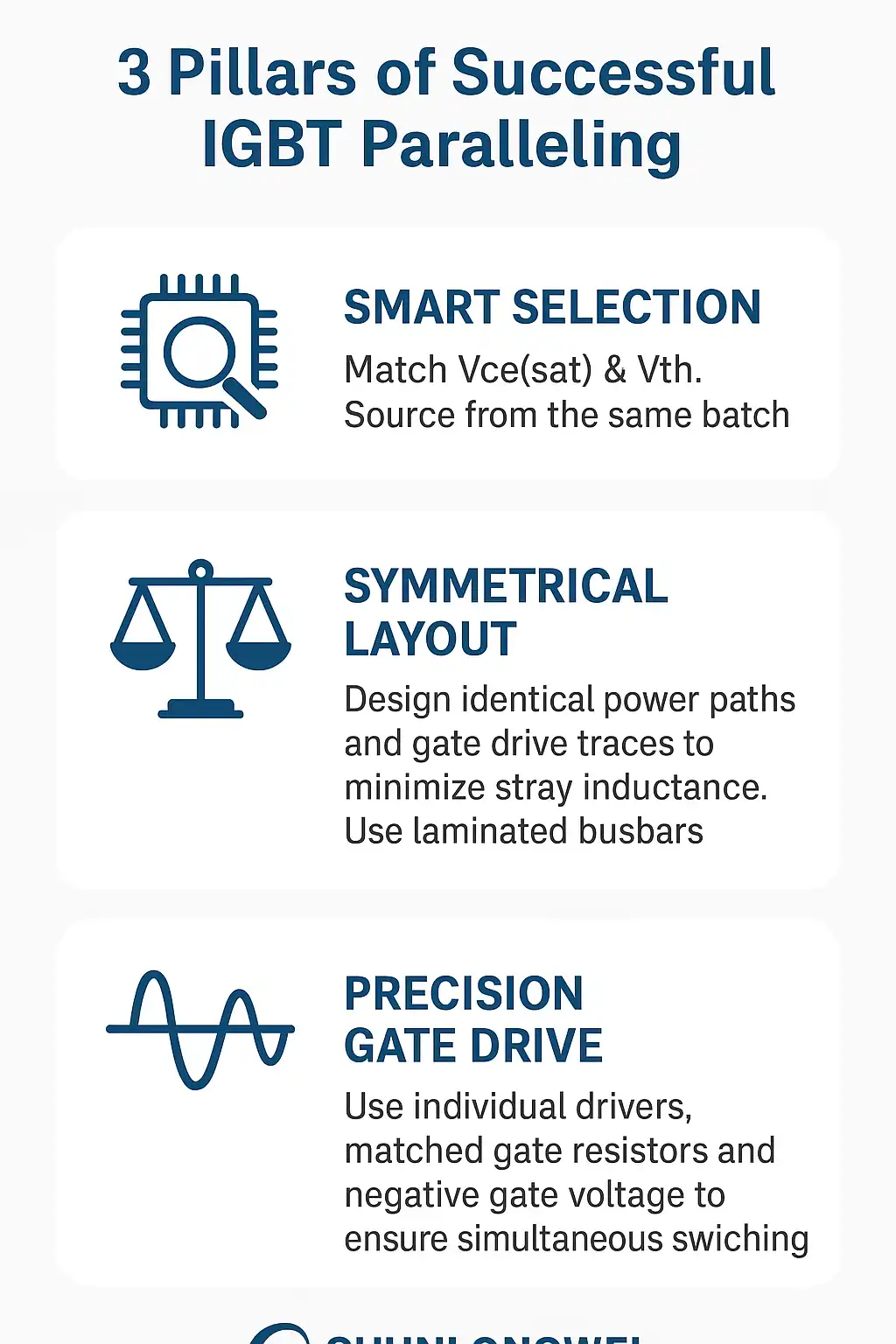
- Title: 3 Pillars of Successful IGBT Paralleling
- Core Concept: A visual guide to achieving reliable current sharing when paralleling IGBT modules in high-power inverters.
- Key Sections & Visuals:
- Point 1: Smart Selection. (Icon: a magnifying glass over a microchip). Key takeaway: Match Vce(sat) & Vth. Source from the same batch.
- Point 2: Symmetrical Layout. (Icon: two balanced scales). Key takeaway: Design identical power paths and gate drive traces to minimize stray inductance. Use laminated busbars.
- Point 3: Precision Gate Drive. (Icon: a waveform signal). Key takeaway: Use individual drivers, matched gate resistors, and negative gate voltage to ensure simultaneous switching.
- Branding: Include Logo: Shunlongwei Co., Ltd. | Website: https://www.slw-ele.com
Related Articles:
- https://www.slw-ele.com/resources/the-core-trio-of-igbt-module-selection-a-practical-guide-to-voltage-current-and-thermal-management
- https://www.slw-ele.com/mastering-igbt-paralleling-a-guide-to-achieving-balanced-current-sharing.html
- https://www.slw-ele.com/ipm-vs-discrete-igbt-a-framework-for-system-cost-and-reliability.html
- https://www.slw-ele.com/from-chip-to-air-a-holistic-approach-to-igbt-thermal-design.html