Packaging Defines the Thermal Ceiling: From Solder-Pin to Press-Fit IGBTs
In the relentless push for higher power density in modern electronics, engineers often focus on the silicon itself—the latest IGBT chip technology promising lower switching losses and higher efficiency. However, the most advanced silicon can be severely bottlenecked by a factor that is frequently underestimated: its package. The packaging of an IGBT module is not merely a protective shell; it is the critical bridge for heat dissipation and the foundation of its long-term reliability. It dictates the absolute thermal ceiling of the application. This article explores the crucial evolution of IGBT packaging, tracing the journey from traditional solder-pin designs to the mechanically robust and thermally superior press-fit technology, and analyzes how this shift redefines performance and reliability in high-power systems.
Deconstructing the Thermal Path: Understanding Thermal Resistance in IGBT Modules
To appreciate the impact of packaging, one must first understand the concept of thermal resistance (Rth). Every material in the path of heat flow from the IGBT chip’s junction to the ambient air presents an obstacle. This cumulative opposition is the total thermal resistance, and minimizing it is the primary goal of thermal management. The heat generated within the silicon chip must traverse several layers, each with its own thermal resistance:
- Rth(j-c) (Junction-to-Case): This is the thermal resistance from the IGBT silicon chip to the module’s baseplate. It is determined entirely by the module’s internal construction—the die attach material (often solder), the Direct Bonded Copper (DBC) substrate, and the solder layer connecting the DBC to the baseplate. This value is inherent to the module’s design and is a key indicator of its thermal performance.
- Rth(c-h) (Case-to-Heatsink): This represents the resistance of the Thermal Interface Material (TIM), or thermal grease, applied between the module’s baseplate and the heatsink. Factors like TIM conductivity, thickness, and surface flatness play a huge role here.
- Rth(h-a) (Heatsink-to-Ambient): This is the resistance of the heatsink itself as it dissipates heat into the surrounding environment, influenced by its size, material, and airflow.
The total junction temperature (Tj), which must be kept below the maximum rating (typically 150°C or 175°C), is a direct function of the power dissipated and this total thermal resistance. For engineers, the Rth(j-c) is particularly important because it is a fixed characteristic of the chosen module. A module with a lower Rth(j-c) can dissipate more heat for the same temperature rise, enabling higher power output or providing a greater safety margin. You can learn more about how to decode IGBT datasheets to find this critical information.
Key Takeaways: The thermal performance of an IGBT module is fundamentally limited by its internal construction, encapsulated by the Rth(j-c) value. Every layer, from the chip’s solder joint to the baseplate, adds to this resistance, making package design a critical factor in effective heat dissipation.
Thermal Path in a Standard IGBT Module
The Workhorse: A Deep Dive into Standard Solder-Pin Packages
For decades, the standard solder-pin module has been the backbone of the power electronics industry. A classic example like the Fuji Electric 2MBI200U4D-120-50 showcases this mature technology: IGBT and diode chips are soldered to a DBC substrate, which is then soldered to a thick copper baseplate. Electrical connections are made via robust solder pins that are manually or wave-soldered to a PCB. This design offers several advantages, including widespread availability, cost-effectiveness, and a proven track record across countless applications.
However, this traditional construction has inherent limitations, particularly concerning reliability. The primary failure mechanism in these modules is fatigue in the solder layers. During operation, the module heats up and cools down, a process known as power cycling. Each material in the module’s stack—silicon, copper, ceramic—has a different Coefficient of Thermal Expansion (CTE). These materials expand and contract at different rates, creating immense mechanical stress on the solder joints that bind them. Over thousands of cycles, this stress leads to micro-cracks that propagate, causing solder layer delamination. This degradation increases the thermal resistance, leading to a higher junction temperature, which in turn accelerates the failure process until thermal runaway occurs.
Key Takeaways: While cost-effective and widely used, solder-pin packages are susceptible to solder fatigue and bond wire lift-off caused by CTE mismatch during thermal cycling. These wear-out mechanisms limit their operational lifetime in applications with frequent and large temperature swings.
The Evolution to Press-Fit Technology: Eliminating the Weakest Link
To overcome the fundamental reliability issues of solder, press-fit technology was developed. This innovative approach eliminates soldering for the module’s connection to the PCB entirely. Instead of solid pins, press-fit modules feature compliant pins, often designed as springs or “eye-of-the-needle” contacts. During assembly, these pins are pressed into plated through-holes on the PCB. The spring action of the pins creates a high-pressure, gas-tight, cold-welded connection.
The Semikron SEMIX151GB12E4V4 is an excellent example of a module utilizing this advanced technology. Its spring-loaded contacts remove the need for a high-temperature soldering process, which immediately provides several benefits:
- Enhanced Reliability: By eliminating the solder joint between the module and the PCB, the primary failure point associated with thermal stress is removed. This dramatically increases the module’s robustness against vibration and thermal cycling.
- Improved Manufacturing: The assembly process is faster, cleaner, and more repeatable than soldering. It avoids thermal stress on the PCB and allows for simple, automated mounting.
- Lower Contact Resistance: The high-pressure connection often results in lower and more stable electrical and thermal resistance compared to a solder joint, improving overall efficiency.
- Serviceability: Modules can be removed and replaced without a complex de-soldering process, simplifying field repairs and system upgrades.
This solder-free interface makes press-fit modules inherently more durable for applications demanding long life and high reliability, such as in electric vehicle inverters, wind turbines, and railway traction systems. Explore further insights into IGBT applications in our guide on the backbone of high-efficiency power systems.
Key Takeaways: Press-fit technology creates a reliable, solder-free connection using mechanical force. This eliminates thermal stress during assembly and removes a key failure mode (solder fatigue), resulting in superior long-term reliability, simplified manufacturing, and improved serviceability.
Head-to-Head Comparison: Solder-Pin vs. Press-Fit IGBT Modules
Choosing the right packaging technology requires a clear understanding of the trade-offs. The decision depends heavily on the specific demands of the application, balancing cost, performance, and long-term reliability.
| Parameter | Standard Solder-Pin Module | Press-Fit Module |
|---|---|---|
| Assembly Process | Requires soldering (wave or manual), which introduces thermal stress to the PCB. Slower process. | Simple mechanical pressing. Fast, clean, automated, and no thermal stress on components. |
| Power Cycling Capability | Limited by solder joint fatigue due to CTE mismatch. A primary wear-out mechanism. | Significantly higher. The compliant pins absorb mechanical stress, leading to much longer life. |
| Vibration Resistance | Good, but solder joints can be susceptible to cracking under severe vibration over time. | Excellent. The high-pressure, compliant connection is inherently more robust against shock and vibration. |
| Initial Cost | Generally lower due to mature technology and manufacturing processes. | Typically higher due to the more complex pin design and precision manufacturing requirements. |
| Total Cost of Ownership | Can be higher in demanding applications due to potential for earlier failure and replacement costs. | Often lower in the long run for high-reliability systems due to increased lifetime and reduced maintenance. |
| Ideal Applications | General-purpose drives, UPS, solar inverters, welding power supplies with moderate power cycling requirements. | Automotive (EV/HEV inverters), wind power, railway traction, high-reliability industrial automation, and servo drives. |
Practical Application Guide: When to Choose Press-Fit Over Solder-Pin
Making the right choice between these two technologies is a critical design decision. Here is a practical framework to guide engineers:
Choose Press-Fit Technology if your application involves:
- High Reliability and Long Lifetime Requirements: For systems where failure is not an option and operational life is expected to exceed 10-15 years, such as in automotive, aerospace, or critical industrial infrastructure, the superior durability of press-fit is a major advantage.
- Frequent and Severe Power Cycling: Applications like electric vehicle main inverters, which undergo constant acceleration and braking, or wind turbines that experience fluctuating loads, will benefit immensely from the enhanced power cycling capability.
- Harsh Operating Environments: Systems exposed to high levels of mechanical shock and vibration, like those in heavy machinery or railway applications, are better served by the robust mechanical connection of press-fit pins.
- Automated, High-Volume Manufacturing: If the production line is highly automated, the speed and repeatability of the press-fit process can lead to higher throughput and lower assembly costs compared to soldering.
Standard Solder-Pin modules remain a viable and cost-effective choice for:
- Cost-Sensitive Projects: For consumer or commercial applications where initial bill-of-materials (BOM) cost is a primary driver and reliability requirements are moderate.
- Stable Operating Conditions: Applications that run continuously with infrequent on/off cycles, such as in some UPS systems or grid-tied equipment, do not heavily stress the solder joints, making standard packages perfectly adequate.
- Legacy Designs and Existing Processes: When upgrading an existing design or when manufacturing facilities are already heavily invested in soldering processes, sticking with solder-pin modules can be the path of least resistance.
Key Takeaways: The selection criteria hinge on a trade-off between initial cost and long-term reliability. Press-fit is the superior choice for applications defined by high stress (thermal or mechanical) and long life requirements, while solder-pin remains the pragmatic option for cost-sensitive projects with moderate operational demands.
Conclusion: The Future of Packaging is Solder-Free and Highly Integrated
The evolution from standard solder-pin to advanced press-fit packaging is more than just an incremental improvement; it represents a fundamental shift in how power modules achieve reliability. By directly addressing the root cause of many field failures—solder fatigue—press-fit technology uncouples the module’s lifetime from the traditional wear-out mechanisms. This allows engineers to push power densities higher and build systems with greater confidence in their long-term performance.
While the silicon chip will always be the heart of an IGBT module, its packaging is undeniably the skeleton that provides mechanical strength and the circulatory system that manages its thermal lifeblood. As the industry moves towards even more demanding applications in e-mobility and renewable energy, solder-free, highly reliable interconnection technologies like press-fit will no longer be a niche option, but the new standard for performance and durability.
Infographic: Solder-Pin vs. Press-Fit: Choosing the Right IGBT Package
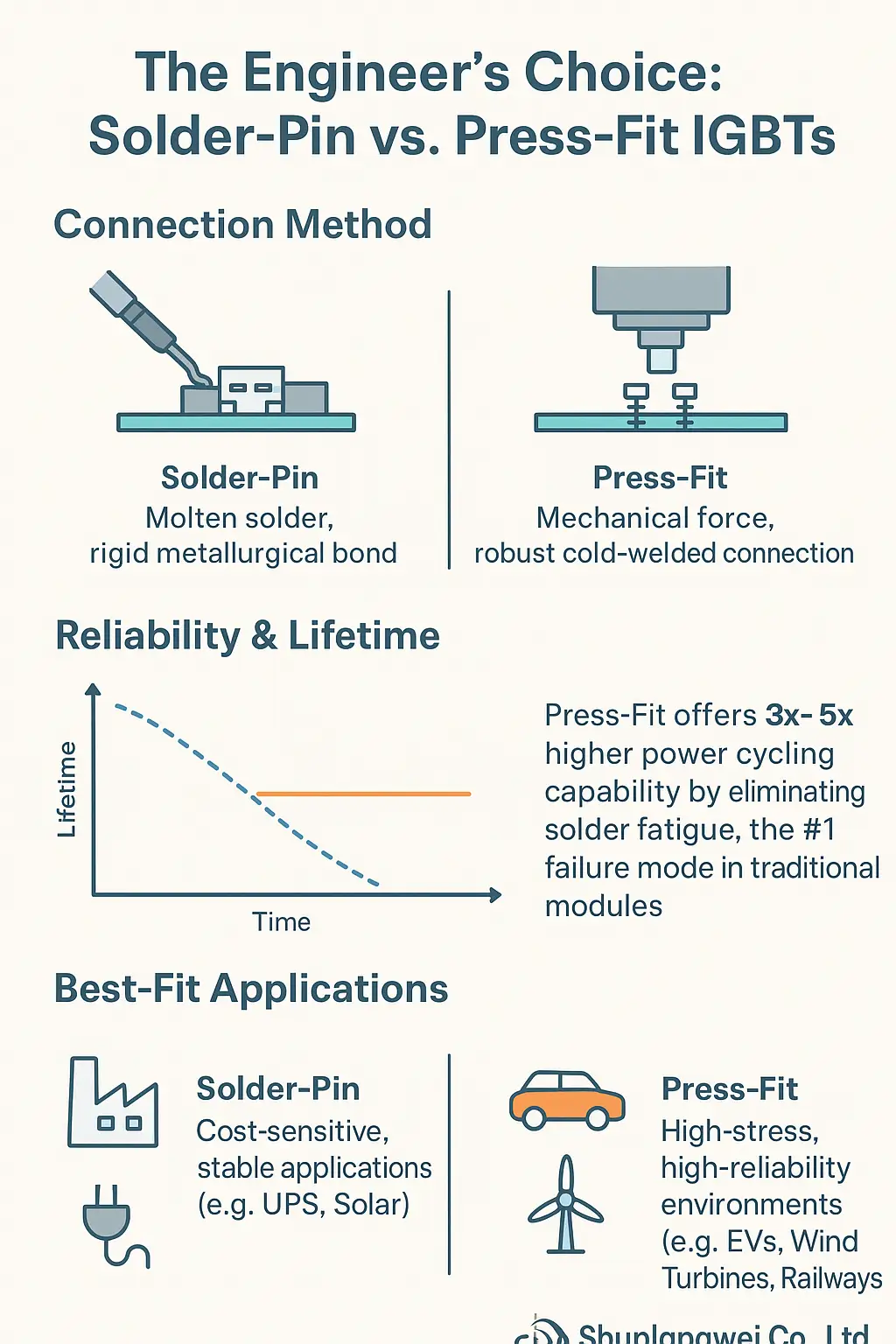
* Title: The Engineer’s Choice: Solder-Pin vs. Press-Fit IGBTs
* Core Concept: A visual comparison guiding engineers on when to choose traditional solder-pin packages versus modern press-fit technology based on application demands.
* Key Sections & Visuals:
* Point 1: Connection Method.
* **Content:** Solder-Pin uses molten solder, creating a rigid metallurgical bond. Press-Fit uses mechanical force with compliant pins, creating a robust, cold-welded connection.
* **Visual:** A side-by-side icon showing a soldering iron next to a solder joint, and a mechanical press pushing a module onto a PCB.
* Point 2: Reliability & Lifetime.
* **Content:** Press-fit offers 3x-5x higher power cycling capability by eliminating solder fatigue, the #1 failure mode in traditional modules.
* **Visual:** A timeline graph showing the expected lifetime of a press-fit module extending far beyond a solder-pin module under heavy cycling conditions.
* Point 3: Best-Fit Applications.
* **Content:** Solder-Pin is ideal for cost-sensitive, stable applications (e.g., UPS, Solar). Press-Fit excels in high-stress, high-reliability environments (e.g., EVs, Wind Turbines, Railways).
* **Visual:** Simple icons representing a factory (industrial), a car (automotive), and a wind turbine for press-fit, versus a power plug (UPS) and sun for solder-pin.
* Branding: Include Logo: Shunlongwei Co., Ltd. | Website: https://www.slw-ele.com