


Content last revised on March 10, 2026
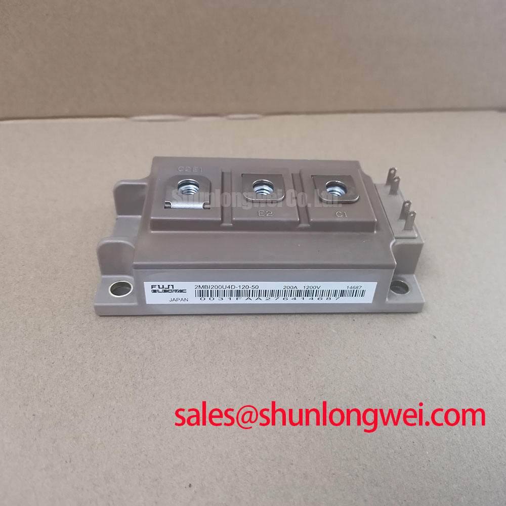
Fuji Electric 2MBI200U4D-120-50 | High-Speed, Low-Loss 1200V Dual IGBT Module
The Fuji Electric 2MBI200U4D-120-50 is a high-performance 1200V, 200A dual IGBT module engineered for demanding power conversion applications. Leveraging Fuji's advanced 4th generation U-series technology, this module strikes an exceptional balance between low conduction losses and high-speed switching, delivering superior efficiency and reliability for modern system designs.
- Voltage and Current Rating: 1200V Collector-Emitter Voltage (Vces) and 200A continuous Collector Current (Ic), providing a robust power handling capability for mid-to-high power systems.
- Low Conduction Loss: Features a very low collector-emitter saturation voltage (VCE(sat)) of 2.2V (typ.), which directly minimizes heat dissipation and improves overall system efficiency.
- High-Speed Switching: Optimized for fast switching frequencies with low turn-on (Eon) and turn-off (Eoff) losses, enabling more compact system designs with smaller passive components.
- Integrated FWD: Includes a soft and fast-recovery freewheeling diode (FWD) co-packaged in the module, ensuring low reverse recovery losses and reduced EMI noise.
Technical Deep Dive: The Engineering Edge
The performance of the 2MBI200U4D-120-50 is rooted in Fuji's sophisticated semiconductor design. The 4th generation U-Series IGBT die utilizes a trench-gate structure combined with a thin wafer field-stop (FS) layer. This architecture fundamentally redefines the trade-off between conduction and switching losses. The trench gate enhances carrier concentration in the channel, significantly lowering the VCE(sat). Simultaneously, the FS layer allows for a thinner N-drift region, which reduces the stored charge and dramatically shortens the switching tail current during turn-off. The result is a device that runs cooler under load and switches faster, a critical advantage in high-frequency power electronics.
Equally important is the integrated freewheeling diode. In hard-switching applications like motor drives, the FWD's reverse recovery characteristic is paramount. This module incorporates a diode optimized for soft recovery behavior. This "softness" mitigates the high di/dt that can induce destructive voltage overshoots and ringing across the IGBT, thereby enhancing the module's Reverse Bias Safe Operating Area (RBSOA) and simplifying the requirements for external snubber circuits.
Application Scenarios and Value Proposition
The specific characteristics of the 2MBI200U4D-120-50 translate into tangible benefits across several key applications:
- Variable Frequency Drives (VFDs): In motor drives, the module's fast switching capability allows for higher PWM frequencies. This leads to reduced motor current ripple, lower audible noise, and improved torque control, while the low VCE(sat) keeps inverter efficiency high.
- AC and DC Servo Drives: Precision and dynamic response are non-negotiable in servo applications. This module's rapid switching and the FWD's low reverse recovery time (trr) enable the high-bandwidth control loops essential for powering precision robotic and CNC systems.
- Uninterruptible Power Supplies (UPS): For UPS systems, reliability and efficiency are the primary metrics. The low total power loss (conduction + switching) of the 2MBI200U4D-120-50 reduces thermal stress, allowing for more compact heatsink designs and improving the long-term operational life of the entire system.
Key Parameter Overview
For a detailed analysis, refer to the official Fuji Electric 2MBI200U4D-120-50 datasheet. The table below summarizes the critical parameters for system design.
| Parameter | Value |
|---|---|
| Collector-Emitter Voltage (Vces) | 1200 V |
| Collector Current (Ic) @ Tc=80°C | 200 A |
| Collector-Emitter Saturation Voltage (VCE(sat)), typ. @ Ic=200A | 2.2 V |
| FWD Forward Voltage (V_F), typ. @ Ie=200A | 1.8 V |
| Thermal Resistance (Rth(j-c)), IGBT per 1/2 module | 0.14 °C/W |
| Package Type | M234 |
Frequently Asked Questions (FAQ)
Q: How does the module's thermal resistance impact system design?
A: The low junction-to-case thermal resistance (Rth(j-c)) of 0.14 °C/W is a significant advantage. It signifies efficient heat transfer from the IGBT die to the module's baseplate. For design engineers, this means that for a given power loss, the junction temperature will be lower, enhancing reliability. To fully leverage this, it is crucial to ensure a low-resistance thermal path from the module to the heatsink by using a high-quality thermal interface material (TIM) and applying appropriate mounting torque.
Q: What are the key gate drive considerations for the 2MBI200U4D-120-50?
A: To achieve the specified fast switching times and prevent issues like parasitic turn-on, a capable gate driver is essential. The driver should provide a recommended gate voltage of +15V for turn-on and a negative voltage (typically -5V to -15V) for a definitive turn-off. The negative bias provides a strong buffer against Miller-capacitance-induced turn-on, especially in half-bridge configurations. For more information on this topic, see our guide on 5 practical tips for robust IGBT gate drive design.