The rapid evolution of the Electric Vehicle (EV) infrastructure is forcing a paradigm shift in power electronics design. As the industry graduates from standard 50 kW chargers to high-power 150 kW and ultra-fast 350 kW DC charging stations, the engineering challenges associated with grid interaction, thermal management, and power density have intensified exponentially. At these elevated power levels, the front-end AC-DC conversion stage is no longer just a rectifier; it is the critical bottleneck that determines the system’s overall efficiency, reliability, and compliance with stringent grid codes.
For power engineers, the transition to 800 V battery architectures necessitates a re-evaluation of traditional topologies. While the conventional two-level, six-switch boost PFC (Power Factor Correction) has been the industry workhorse, it faces significant limitations when scaling to higher voltages and power densities. This is where the Vienna Rectifier—a three-phase, three-level PWM rectifier—has established itself as a superior alternative. This article provides an in-depth technical analysis of the Vienna Rectifier’s operation mechanisms, its strategic advantage in utilizing 600 V discrete components for high-voltage buses, and why it is becoming the topology of choice for next-generation charging infrastructure.
The Physics of High-Power PFC: Why Topologies Matter
In the context of a 150 kW charging station, the primary objective of the PFC stage is to convert the three-phase AC grid voltage (typically 400 VAC or 480 VAC) into a stable, regulated DC link voltage (typically 800 VDC to 900 VDC), while ensuring that the input current remains sinusoidal and in phase with the grid voltage.
The “Power Factor” is not merely a regulatory metric; it is a measure of utilization efficiency. A low power factor implies that the charger is drawing reactive power that performs no useful work but heats up the cabling and transformers. Furthermore, high-power non-linear loads can inject harmonic currents into the grid, causing voltage distortion that affects other equipment. Standards such as IEEE 519 and IEC 61000-3-12 impose strict limits on Total Harmonic Distortion (THD), often requiring it to be below 5% at full load.
To understand why the Vienna Rectifier is favored, we must first look at the limitations of the standard two-level active frontend. In a two-level topology, the switching node transitions between the full positive DC rail and the negative DC rail. This creates a large voltage step ($\Delta$V = VDC) with every switching event. This high dV/dt results in:
- Larger Inductors: To keep the current ripple within acceptable limits, the input boost inductors must be physically large and heavy.
- Higher EMI: Large voltage jumps generate significant high-frequency noise, requiring heavy EMI filtering.
- Component Stress: The switches must be rated to block the full DC link voltage, plus a safety margin.
For a deeper understanding of how these high-voltage architectures are influencing component selection, you can refer to our analysis on unlocking ultra-fast charging and the role of IGBTs in 800V platforms.
Deconstructing the Vienna Rectifier: A Three-Level Approach
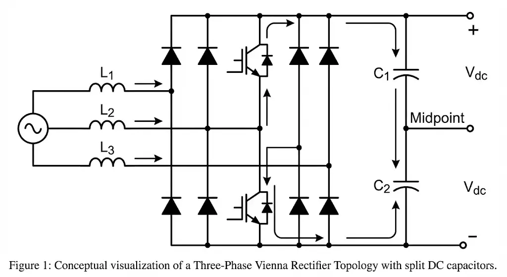
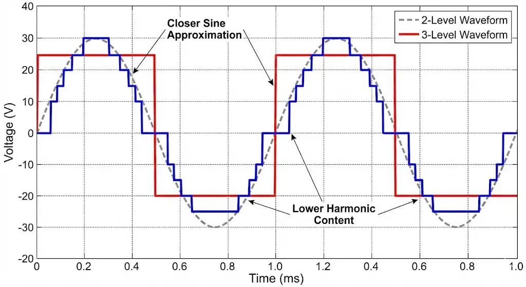
The Vienna Rectifier distinguishes itself as a three-level topology. Unlike the two-level converter, the Vienna Rectifier can generate three distinct voltage levels at its input terminals relative to the DC midpoint: Positive (+VDC/2), Zero (Neutral), and Negative (-VDC/2).
The Operating Mechanism
The topology achieves this using a unique switch arrangement. It typically consists of three active switches (one per phase) and a specific diode configuration. The DC link is split by two capacitors in series, creating a stable center point (neutral).
The operation can be visualized in three modes for each phase, depending on the current direction and switch state:
- Switch ON: When the active switch for a phase is turned ON, the phase input is connected to the neutral point of the DC bus. The voltage across the inductor is the phase voltage, causing the current to build up. This is the energy storage phase.
- Switch OFF (Positive Half-Cycle): If the phase current is positive and the switch is OFF, the current flows through the high-side diode to the positive DC rail.
- Switch OFF (Negative Half-Cycle): If the phase current is negative and the switch is OFF, the current flows through the low-side diode from the negative DC rail.
By modulating the duty cycle of the switch, the average voltage at the rectifier input can be controlled to form a sinusoidal shape. Because the voltage steps only transition between 0 and VDC/2 (rather than 0 and VDC), the ripple current in the inductors is drastically reduced—often by a factor of four for a given switching frequency. This allows engineers to use significantly smaller magnetic components, which improves power density.
The Economic Masterstroke: Utilizing 600 V Discrete Components
One of the most compelling reasons to adopt the Vienna Rectifier for 150 kW+ applications is the optimization of the Bill of Materials (BOM) cost, specifically regarding power semiconductors.
In a typical 150 kW charger designed for 800 V EVs, the internal DC link voltage might be boosted to 900 V or higher to ensure current flows into the battery. In a standard two-level topology, the switches must block this full 900 V. Engineering best practices dictate a safety margin, requiring devices rated for at least 1200 V.
The Vienna Advantage: Due to the connection to the capacitive midpoint, the voltage stress across the active switches in a Vienna Rectifier is clamped to half the DC link voltage. For a 900 V bus, the switch sees only 450 V. This geometric advantage allows engineers to utilize 600 V or 650 V rated devices.
Silicon Superjunction MOSFETs vs. SiC
This voltage reduction opens the door to mature, mass-produced Silicon Superjunction (SJ) MOSFETs. These components are:
- Cost-Effective: 600 V SJ-MOSFETs are significantly less expensive than 1200 V Silicon Carbide (SiC) MOSFETs.
- High Performance: Modern 600 V MOSFETs offer exceptionally low on-resistance (RDS(on)), reducing conduction losses.
- Available: The supply chain for 600 V silicon is vast and stable.
While 1200 V SiC devices offer excellent switching speeds, their cost per ampere is higher. By using a topology that permits 600 V devices, designers can achieve high efficiency at a lower system cost. For a detailed comparison of these semiconductor technologies, refer to our technical guide on Si vs. SiC vs. GaN switching speeds and power losses.
Furthermore, even if a designer chooses to use SiC for its thermal benefits, 650 V SiC devices are cheaper and often have better Figures of Merit (FOM) than their 1200 V counterparts. This flexibility in component selection is a key reason why the Vienna topology dominates the 150 kW+ charging market.
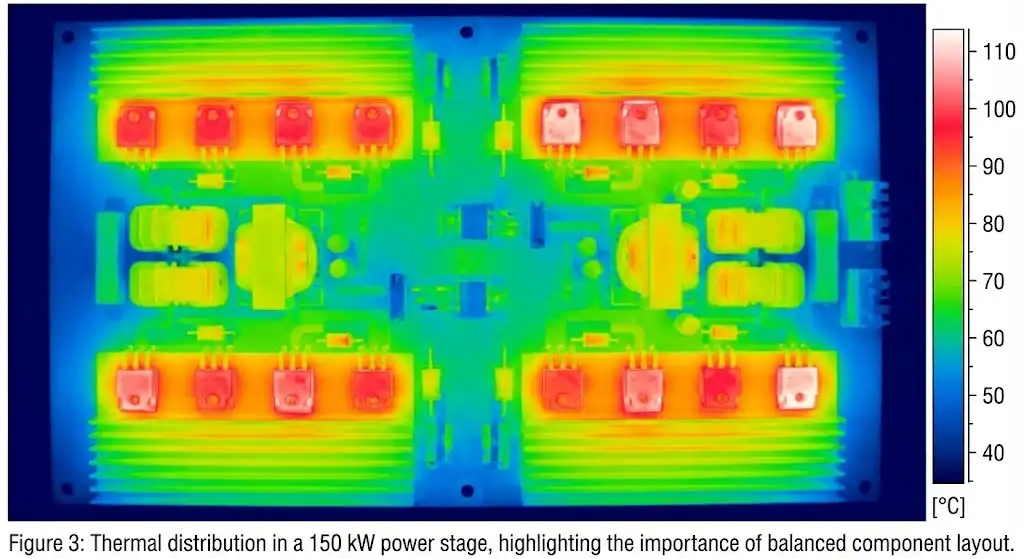
Efficiency Analysis: Where the Losses Go
In high-power electronics, thermal management is a primary constraint. A 150 kW converter operating at 95% efficiency generates 7500 Watts of heat—enough to heat a large home. Increasing that efficiency to 98% reduces the waste heat to 3000 Watts, drastically simplifying the cooling system.
The Vienna Rectifier contributes to this efficiency gain through several mechanisms:
- Reduced Switching Losses: Since the voltage switched is only VDC/2, the energy lost during the turn-on and turn-off transitions is significantly lower compared to a 2-level converter switching the full VDC.
- Zero Current Switching (ZCS) Potential: With advanced control schemes, the topology can operate in discontinuous conduction modes near the zero crossings, further minimizing losses.
- Diode Selection: The efficiency of the Vienna Rectifier is heavily dependent on the diodes. The high-side and low-side diodes carry the current during the freewheeling phase. Using SiC Schottky diodes here virtually eliminates reverse recovery losses (Qrr), which are a major source of heat in silicon diodes.
For engineers selecting modules, understanding the trade-offs between integrated modules and discrete designs is vital. You can explore more on this in our article discussing the engineer’s ultimate guide to IGBT modules, which covers thermal behaviors relevant to high-power rectifiers.
Control Challenges and Solutions
While the hardware benefits are clear, the Vienna Rectifier introduces complexity in the control domain. It is not a “plug-and-play” solution. The controller must manage:
- Input Current Shaping: Ensuring the current follows the voltage waveform for Unity Power Factor.
- DC Bus Voltage Regulation: Maintaining the total output voltage at the setpoint.
- Neutral Point Balancing: This is unique to three-level topologies. The controller must actively balance the voltage across the two split capacitors. If the midpoint drifts (e.g., +600 V on top and -200 V on bottom), it stresses the components and distorts the input current.
Modern digital signal controllers (DSCs) handle this using Space Vector Modulation (SVM) or hysteresis control. The control loop must also handle the transition between continuous conduction mode (CCM) and discontinuous conduction mode (DCM) near the AC zero-crossings, where Vienna Rectifiers are prone to current distortion known as “cusp distortion.”
Design Considerations for 150 kW+ Systems
When designing a 150 kW system, the rectifier is often built using paralleled modules. For instance, three 50 kW Vienna Rectifier modules might be interleaved. This interleaving further cancels out ripple currents, reducing the stress on the input capacitors.
Component Selection Guide
1. Active Switches:
For 150 kW, discrete TO-247 packages are often paralleled, or power modules are used. If using MOSFETs, ensure the body diode is rugged, although in the Vienna topology, the MOSFET body diode does not conduct load current, which is a significant reliability advantage over other topologies. For a broader view on MOSFET selection, see our Power MOSFET Deep Dive.
2. Input Inductors:
Because of the three-level operation, the inductor sees a frequency that is effectively double the switching frequency in terms of ripple. This allows the use of powder cores or ferrite cores with lower permeability, reducing core losses.
3. Protection:
High-power systems require robust protection against overcurrent and overvoltage. Inrush current limiting is critical because the split DC capacitors must be charged evenly. A mismatch during startup can trigger overvoltage protection.
Comparison: Vienna Rectifier vs. Active Front End (AFE)
It is important to note that the Vienna Rectifier is a unidirectional topology. Power flows from the grid to the vehicle, but not vice versa.
As the concept of Vehicle-to-Grid (V2G) gains traction, bidirectional chargers are needed. These require a full Active Front End (AFE), typically a two-level or three-level active bridge (like a T-type or NPC inverter running in reverse). However, for dedicated rapid charging stations where the primary goal is throughput (filling the battery as fast as possible), unidirectionality is not a drawback; it is a feature that simplifies control and reduces hardware cost.
If your application requires examining alternative high-voltage designs, such as those using 1200 V devices for potentially bidirectional flows, our resource on designing 150kW DC fast chargers with 1200V IGBTs provides a contrasting perspective on full-bridge topologies.
Conclusion
The Vienna Rectifier represents a “sweet spot” in power electronics engineering for 150 kW+ EV charging stations. It effectively balances the need for high efficiency and low harmonic distortion with the economic reality of component costs. By leveraging the three-level switching principle, it allows engineers to utilize mature, cost-effective 600 V power semiconductors in high-voltage 800 V applications, avoiding the premium of high-voltage SiC devices while still delivering superior performance.
As the EV market continues to demand faster charging times and higher power densities, mastering topologies like the Vienna Rectifier is essential for any power electronics engineer. The future of charging infrastructure lies not just in more power, but in smarter, more efficient power conversion.
References & Further Technical Reading
To ensure the accuracy of your designs and to dive deeper into specific subsystem parameters, we recommend consulting the following authoritative resources:
- Texas Instruments – Vienna Rectifier-Based Three Phase Power Factor Correction Reference Design: A practical implementation guide for digital control of Vienna Rectifiers.
- IEEE Xplore – Analysis and Design of Vienna Rectifier for High Power Applications: Peer-reviewed research detailing the mathematical modeling and loss analysis.
- Infineon Technologies – Application Note: Vienna Rectifier Power Topology: Detailed semiconductor selection guidelines and thermal considerations.
- Wolfspeed – Designing a Vienna Rectifier with SiC: An analysis of how Silicon Carbide further enhances this topology.