More Than Just Vce(sat): A Deep Dive into Optimizing Inverter Efficiency with IGBT Dynamic Switching Parameters (Eon, Eoff, Qrr)
For years, engineers have relied on collector-emitter saturation voltage (Vce(sat)) as the primary metric for selecting IGBTs. In low-frequency applications like motor drives, this makes sense; conduction losses, which are directly proportional to Vce(sat), are the dominant factor in overall efficiency. However, in the world of high-frequency power conversion—such as in advanced inverter welding machines, solar inverters, and uninterruptible power supplies (UPS)—this Vce(sat)-centric approach is dangerously incomplete. At switching frequencies of 20 kHz, 50 kHz, or even higher, the hidden killer of efficiency isn’t conduction loss, it’s switching loss.
Switching losses occur during the brief moments the IGBT transitions between on and off states. While individually small, these losses accumulate rapidly as frequency increases, often becoming the largest source of heat and inefficiency in the system. This is where a deeper understanding of dynamic parameters becomes critical. The turn-on energy (Eon), turn-off energy (Eoff), and the freewheeling diode’s reverse recovery charge (Qrr) are the true determinants of high-frequency performance. Mastering how to interpret and apply these datasheet values is the key to unlocking higher efficiency, reducing heatsink size, and building more reliable, power-dense inverters.
Deconstructing the Switch: A Breakdown of IGBT Dynamic Parameters
To move beyond a superficial Vce(sat) analysis, we must dissect the switching event itself. The total energy lost during each cycle is a combination of three interconnected phenomena. A thorough grasp of IGBT structure and technology provides the foundation for understanding these dynamic behaviors.
What is Turn-On Energy (Eon)?
Turn-on energy (Eon) is the total energy dissipated within the IGBT during the transition from the blocking (off) state to the conducting (on) state. This isn’t an instantaneous event. It involves charging the IGBT’s internal capacitances and a critical phase where both voltage across the device is high and current through it is rising. A significant, and often overlooked, contributor to Eon is the behavior of the freewheeling diode (FWD) in the opposing leg of the inverter bridge. As the IGBT turns on, it must handle not only the load current but also a transient “reverse recovery” current from the FWD, which adds substantially to the turn-on power spike.
Understanding Turn-Off Energy (Eoff)
Turn-off energy (Eoff) is the energy lost when the IGBT transitions from on to off. This process is characterized by the notorious “tail current.” Because the IGBT is a minority carrier device, it takes time to sweep all the charge carriers out of the drift region to return it to a non-conductive state. During this “tail” period, a residual current continues to flow even as the voltage across the device is rising to the full DC bus level. This simultaneous high-voltage, moderate-current condition creates a significant loss pulse, which is quantified as Eoff. IGBTs designed for speed often employ techniques to shorten this tail current, directly reducing Eoff.
The Critical Role of Reverse Recovery Charge (Qrr)
While technically a parameter of the anti-parallel freewheeling diode, the reverse recovery charge (Qrr) has a profound impact on the IGBT’s performance. When a diode switches from forward conduction to a reverse blocking state, it doesn’t stop conducting immediately. A reverse current flows for a short duration to remove the stored charge in the diode. This reverse current spike in the diode directly adds to the turn-on current of the complementary IGBT in a half-bridge. A diode with a high Qrr will cause a larger current spike in the opposing IGBT, dramatically increasing its Eon. Therefore, for hard-switching, high-frequency applications, selecting an IGBT module with a “soft” and fast-recovery diode (low Qrr) is just as important as the IGBT’s own switching characteristics.
Key Takeaways: The Interplay of Dynamic Parameters
It’s crucial to understand that Eon, Eoff, and Qrr are deeply interconnected. A high Qrr from the freewheeling diode will directly inflate the Eon of the switching IGBT. Therefore, optimizing a high-frequency inverter is not just about finding a low Eoff IGBT; it’s about selecting a balanced module where both the IGBT chip and the diode are optimized for speed, resulting in low Eon, Eoff, and Qrr collectively.
Reading Between the Lines: How to Interpret Datasheet Curves for Eon, Eoff, and Qrr
The numbers listed in the main electrical characteristics table of a datasheet are just a starting point. To truly predict performance, engineers must dive into the graphical data. Our guide on decoding IGBT datasheets provides a comprehensive overview of this essential skill.
Locating the Key Information
In any modern IGBT module datasheet, like that for the Infineon FS450R12KE3, you will find a section dedicated to switching characteristics. Look for graphs titled “Typical Switching Energy vs. Collector Current,” “Typical Switching Energy vs. Gate Resistor,” and “Typical Reverse Recovery vs. di/dt.” These graphs contain the nuanced data needed for accurate loss calculations.
Analyzing the Dependency Curves
- Eon/Eoff vs. Collector Current (Ic): This is the most critical graph. It shows that switching losses are not constant but increase, often linearly, with the current being switched. Your loss calculation must use the energy values corresponding to your application’s actual operating current.
- Eon/Eoff vs. Gate Resistance (Rg): This curve demonstrates the trade-off between switching speed and control. A lower Rg speeds up the switching, which generally reduces Eoff. However, it can also lead to higher voltage overshoots and EMI. Eon, conversely, often increases with lower Rg because it causes the diode to recover more abruptly (higher di/dt). This highlights the importance of gate drive design in loss optimization.
- Eon/Eoff vs. Junction Temperature (Tj): Switching losses typically increase with temperature. A design that runs hot will have higher switching losses, which in turn creates more heat—a potential thermal runaway scenario. Your calculations should be based on the expected steady-state operating temperature.
A Practical Example: Calculating Switching Losses
The total switching power loss (P_sw) can be estimated with a straightforward formula:
P_sw = (Eon + Eoff + Erec) * f_sw
Where Erec is the reverse recovery energy of the diode (related to Qrr) and f_sw is the switching frequency.
Let’s imagine an application running at 50 kHz with a peak current of 150A and a DC bus of 600V.
- Find the “Switching Energy vs. Collector Current” graph in the datasheet.
- At Ic = 150A, find the corresponding values for Eon, Eoff, and Erec at your operating temperature (e.g., Tj=125°C). Let’s say they are Eon=8mJ, Eoff=6mJ, and Erec=4mJ.
- Calculate total energy per cycle: E_total = 8mJ + 6mJ + 4mJ = 18mJ.
- Calculate total switching power: P_sw = 18mJ * 50,000 Hz = 900 Watts.
This 900W is pure heat that your thermal management system must dissipate, demonstrating why these “small” energy values become enormously significant at high frequencies.
Key Takeaways: From Datasheet to Design
Never rely solely on the headline numbers. Datasheet values are reference points tested under specific conditions. Real-world performance is dictated by your exact operating current, temperature, and gate drive design. Accurate loss estimation requires a careful interpretation of these characteristic curves, not just a single value from a table.
Application in Focus: Selecting the Right IGBT for a High-Frequency Welding Inverter
High-frequency inverter welding machines are a perfect case study for the importance of dynamic parameters. They operate at high frequencies (typically >50 kHz) to reduce the size of the magnetic components and provide a stable welding arc.
The Problem: Balancing Conduction and Switching Losses at 50kHz+
An engineer focused only on Vce(sat) might choose an IGBT optimized for motor drives. This device would have excellent low conduction losses. However, when operated at 50 kHz, its high Eon and Eoff values would lead to massive switching losses, causing rapid overheating and potential failure. In this scenario, switching losses can account for 60% or more of the total losses.
The Solution: Prioritizing Dynamic Performance
A smarter approach involves comparing two types of IGBTs based on their intended application. The key is to analyze the trade-off between static and dynamic losses, a fundamental concept explained in resources like the Infineon TRENCHSTOP™ IGBT3 application note.
| Parameter | Device A: Fast-Switching (e.g., Mitsubishi CM300DY-12NF) | Device B: Low Vce(sat) (Standard Motor Drive IGBT) |
|---|---|---|
| Target Application | High-Frequency Inverters, Welders, UPS | Low-Frequency Motor Drives |
| Vce(sat) @ nominal Ic | 2.2V (Higher) | 1.7V (Lower) |
| Eon + Eoff @ nominal Ic, 125°C | 10 mJ (Low) | 25 mJ (High) |
| Diode Qrr | Low | Standard / High |
The Result: Quantifying the Efficiency Gain
Let’s calculate the total losses for both devices in a 200A, 50kHz welding application with a 50% duty cycle.
- Device A (Fast-Switching):
- P_cond = 2.2V * 200A * 0.5 = 220 W
- P_sw = 10mJ * 50,000 Hz = 500 W
- P_total = 720 W
- Device B (Low Vce(sat)):
- P_cond = 1.7V * 200A * 0.5 = 170 W
- P_sw = 25mJ * 50,000 Hz = 1250 W
- P_total = 1420 W
The result is striking. The fast-switching IGBT, such as the CM300DY-12NF, has nearly half the total power loss of the device with the lower Vce(sat). This translates directly into higher system efficiency, a much smaller and cheaper heatsink, and significantly improved long-term reliability.
Key Takeaways: Match the IGBT to the Frequency
The core lesson is clear: for high-frequency applications (>20 kHz), the selection priority must shift from Vce(sat) to Eon, Eoff, and Qrr. Conversely, for low-frequency applications where the device spends most of its time conducting, Vce(sat) rightfully remains the most critical parameter.
Conclusion: Beyond Vce(sat) for Smarter Power Design
While Vce(sat) is a foundational parameter for calculating conduction losses, it tells only half the story. In the push for higher power density and efficiency, inverter designs are increasingly moving to higher switching frequencies. In this landscape, a mastery of dynamic parameters—Eon, Eoff, and Qrr—is what separates a successful, reliable design from one that is destined for thermal failure. By learning to look beyond the headline Vce(sat) value and critically analyzing the switching energy curves in a datasheet, engineers can make far more intelligent selection decisions. This holistic approach, which balances both static and dynamic switching losses, is essential for optimizing the next generation of high-performance power inverters. Utilizing advanced features like a Kelvin Emitter connection can further enhance switching performance by minimizing gate loop inductance.
For expert assistance in selecting the ideal IGBT for your high-frequency application, such as the fast-switching CM300DY-12NF or the versatile FS450R12KE3, contact the Shunlongwei technical team.
Infographic: Decoding IGBT Dynamic Parameters for Optimal Efficiency
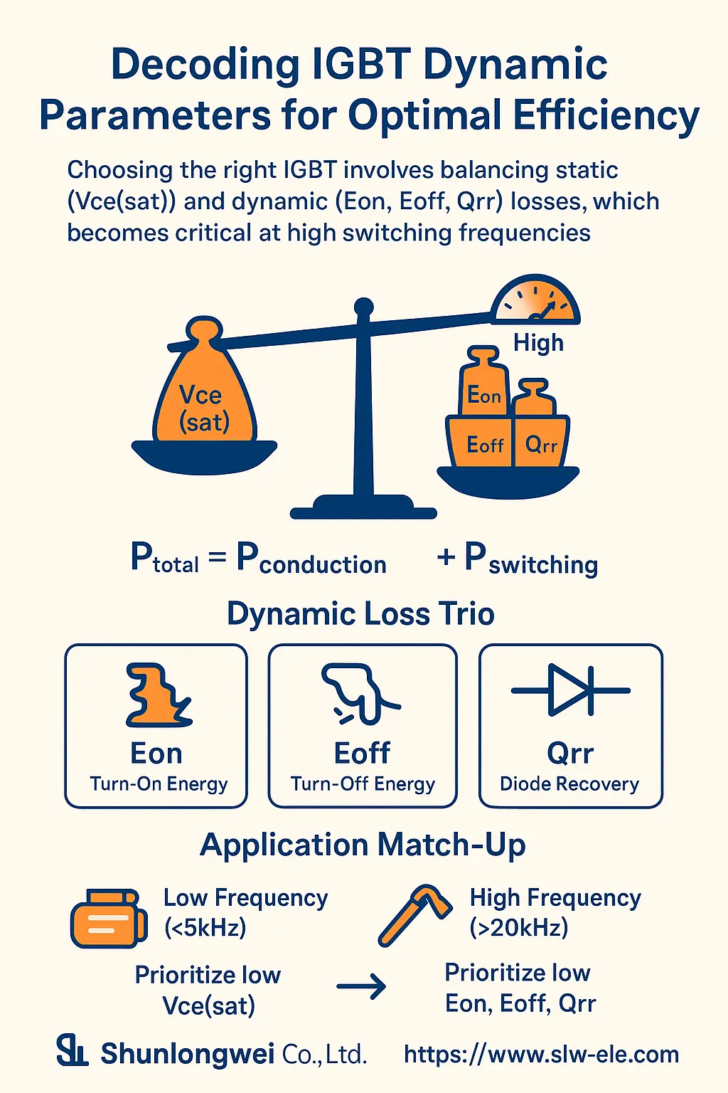
- Title: Decoding IGBT Dynamic Parameters for Optimal Efficiency
- Core Concept: Choosing the right IGBT involves balancing static (Vce(sat)) and dynamic (Eon, Eoff, Qrr) losses, which becomes critical at high switching frequencies.
- Key Sections & Visuals:
- Point 1: The Loss Equation: P_total = P_conduction + P_switching. Visual: A balancing scale with a “Vce(sat)” weight on one side and “Eon, Eoff, Qrr” weights on the other. Include a frequency dial icon pointing to “High,” tilting the scale towards the switching loss side.
- Point 2: Dynamic Loss Trio: Briefly define Eon (Turn-On Energy), Eoff (Turn-Off Energy), and Qrr (Diode Recovery). Visual: Three distinct icons—a switch closing with an energy burst, a switch opening with a “tail,” and a diode symbol with a reverse current arrow.
- Point 3: Application Match-Up: Show two paths. Path 1: Low Frequency (<5kHz) with a motor icon, leading to “Prioritize low Vce(sat)”. Path 2: High Frequency (>20kHz) with a welding torch icon, leading to “Prioritize low Eon, Eoff, Qrr”.
- Branding: Include Logo: Shunlongwei Co., Ltd. | Website: https://www.slw-ele.com
Related Articles:
- Beyond the Datasheet: A Systematic Guide to High-Power IGBT Thermal Design
- More Than Just Vce(sat): A Deep Dive into Optimizing Inverter Efficiency with IGBT Dynamic Switching Parameters (Eon, Eoff, Qrr)
- IPM vs. Discrete IGBT: A Decision Guide for Power Drive Design
- Beyond the Silicon: How IGBT Packaging Dictates Thermal Performance and Reliability