From Datasheet to Reality: A Systematic Engineering Approach to High-Power IGBT/IPM Module Selection and Thermal Design
Introduction: Why V/A Ratings Are Just the Tip of the Iceberg
In the world of high-power electronics, selecting an IGBT or IPM module solely based on its voltage and current ratings is like choosing a race car based only on its paint color. While these headline numbers are a starting point, they reveal nothing about the component’s ability to perform reliably under the immense thermal stress of real-world applications. As industrial automation and renewable energy systems push for ever-higher power densities, a superficial selection process is a direct path to premature failure, system downtime, and costly redesigns. The true mark of a robust design lies in a systematic engineering approach that goes beyond the datasheet’s cover page to rigorously analyze thermal performance.
This article provides a comprehensive framework for engineers and technical managers to move from basic specifications to a deep understanding of thermal reality. We will deconstruct the critical electrical parameters that generate heat, demystify the all-important thermal resistance (Rth) value, and provide a practical guide to thermal management. By understanding how module packaging, technology, and system-level cooling interact, you can make informed decisions that balance performance, cost, and long-term reliability. A deeper appreciation for these concepts is fundamental to mastering power system design, as outlined in this in-depth analysis of IGBT structure.
Deconstructing the Datasheet: Key Electrical Parameters Beyond the Basics
The foundation of any thermal analysis is understanding the sources of heat. In an IGBT module, power loss (P_loss), which is converted directly into heat, is the sum of two primary components: conduction losses and switching losses. A failure to accurately calculate these losses will render any subsequent thermal design useless.
Conduction Losses: The Impact of Vce(sat)
Conduction loss is the heat generated when the IGBT is in its “on” state, allowing current to flow through it. This loss is determined by the collector-emitter saturation voltage, or Vce(sat). Think of Vce(sat) as the small voltage drop that occurs across the switch when it’s closed. The power dissipated during this phase is calculated simply as P_cond = Vce(sat) * Ic * Duty Cycle. While the formula is simple, Vce(sat) is a dynamic value that is influenced by several factors:
- Collector Current (Ic): Vce(sat) increases as the collector current rises. Datasheets provide curves showing this relationship, which is essential for accurate loss calculation across the entire load range of your application.
- Junction Temperature (Tj): Modern trench-gate IGBTs have a positive temperature coefficient for Vce(sat), meaning the saturation voltage increases as the chip gets hotter. While this slightly increases losses at high temperatures, it is a crucial feature for paralleling modules, as it helps prevent thermal runaway.
- Gate-Emitter Voltage (Vge): Applying the manufacturer-recommended gate voltage (typically +15V) is critical to fully “turn on” the IGBT and achieve the lowest possible Vce(sat).
Switching Losses: The Eon, Eoff, and Erec Triangle
Switching losses occur during the brief transitions between the “on” and “off” states. Unlike conduction losses, which dominate in low-frequency applications like motor drives, switching losses become the primary source of heat as frequency increases into the tens of kilohertz, typical of applications like high-frequency welders or solar inverters. These losses are a combination of:
- Turn-on Energy (Eon): The energy lost as the IGBT transitions from a blocking state to a conducting state.
- Turn-off Energy (Eoff): The energy lost when transitioning from conducting to blocking. This is often the largest component of switching loss due to the “tail current” phenomenon in IGBTs.
- Reverse Recovery Energy (Erec): Energy lost in the freewheeling diode that is paired with the IGBT.
The total switching power loss is calculated as P_sw = (Eon + Eoff + Erec) * f_sw, where f_sw is the switching frequency. It’s clear from this formula that switching losses are directly proportional to frequency, making them a critical consideration in high-frequency designs.
Key Takeaways: The total power dissipated by the module is the sum of conduction and switching losses. A fundamental trade-off exists in IGBT chip design: devices optimized for low Vce(sat) (low conduction losses) often have slower switching speeds and higher switching losses, and vice-versa. Your application’s operating frequency is the primary factor in determining which type of loss will dominate.
The Thermal Bottleneck: Understanding the Critical Role of Rth(j-c)
Once you’ve calculated the total power loss (heat) being generated, the next challenge is getting that heat away from the semiconductor chip. This is where the concept of thermal resistance becomes the single most important factor in module selection. Thermal resistance, denoted Rth, is a measure of how difficult it is for heat to flow from one point to another. A lower Rth value signifies better heat transfer. For a power module, the thermal path is a series of resistances:
What is Thermal Resistance (Rth)? A Simple Analogy
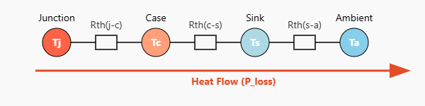
Think of the flow of heat as analogous to the flow of electricity. Power loss (heat) is like current, temperature difference is like voltage, and thermal resistance is like electrical resistance. The fundamental equation governing this is Tj = Ta + P_loss * Rth_total, where:
- Tj: Junction Temperature – The actual temperature of the semiconductor chip. This is the critical value that must be kept below the datasheet maximum (e.g., 150°C or 175°C).
- Ta: Ambient Temperature – The temperature of the surrounding environment (e.g., air or liquid coolant).
- P_loss: The total power loss (conduction + switching) calculated earlier.
- Rth_total: The sum of all thermal resistances in the path: Rth(j-c) + Rth(c-s) + Rth(s-a).
Why Rth(j-c) is the Most Critical Parameter in the Datasheet
While you have control over the heatsink (Rth(s-a)) and thermal interface (Rth(c-s)), the junction-to-case thermal resistance, Rth(j-c), is an intrinsic property of the module itself. It represents the thermal resistance from the silicon chip (junction) to the module’s baseplate (case). This value is determined by the manufacturer’s design, materials (like the ceramic substrate and copper baseplate), and assembly processes. A module with a lower Rth(j-c) can dissipate heat from the chip to the heatsink more effectively, allowing it to handle more power or run cooler at the same power level. This concept is so vital that it forms the core of unlocking an IGBT’s true potential, a topic explored further in Why Rth Matters: Unlocking IGBT Thermal Performance.
Calculating Junction Temperature (Tj): The Core of Reliability
The ultimate goal of thermal design is to ensure that the calculated Tj never exceeds the specified maximum under worst-case operating conditions (maximum load, maximum ambient temperature). Exceeding Tjmax, even for brief periods, can drastically reduce the module’s lifespan and lead to catastrophic failure. The thermal resistance calculation is the engineering tool that connects your paper design to physical reliability.
Key Takeaways: Rth(j-c) is a fixed parameter for a given module and is the primary indicator of its intrinsic thermal performance. Your design goal is to select a module and design a cooling system (heatsink and TIM) such that the calculated junction temperature (Tj) remains safely below its maximum limit under all operating conditions.
A Comparative Analysis: Module Packaging and Technology Impact on Thermal Performance
The choice of module technology and packaging has a profound impact on thermal resistance and overall system design complexity. Simply comparing two 1200V/75A modules is insufficient; their internal construction dictates their real-world performance.
Standard Industrial Modules vs. Advanced Packaging
A workhorse module like the FS75R12KT4_B15 represents a standard, flexible solution widely used in motor drives. It features a copper baseplate and an Al2O3 substrate, offering a balance of performance and cost. Advanced modules may use materials like Aluminum Nitride (AlN) or Silicon Nitride (Si3N4) for the substrate, which offer significantly higher thermal conductivity than Al2O3, resulting in a lower Rth(j-c) but at a higher cost.
The IPM Advantage: Integrated Design, Thermal Challenges
Intelligent Power Modules (IPMs) like the SKiiP 13AC12T4V1 integrate the IGBTs, freewheeling diodes, gate drivers, and protection circuits into a single housing. This significantly simplifies design and enhances reliability. Many modern IPMs from manufacturers like Semikron utilize baseplate-less designs. This approach eliminates one thermal resistance layer (the baseplate-to-heatsink interface), allowing for a more direct and efficient heat path to the heatsink. However, it requires a very flat and smooth heatsink surface to be effective.
High-Voltage, High-Power Considerations
For megawatt-scale applications, modules like the 4500V CM900HC-90H or the 1700V 6MBI450V-170-50 are used. These modules are physically larger to accommodate the larger silicon die needed for high voltage blocking and to spread the immense heat load over a wider area. Their internal construction is highly optimized to achieve the lowest possible Rth(j-c), as even a small thermal resistance can lead to a significant temperature rise given the massive power losses involved.
| Feature | Standard IGBT (e.g., FS75R12KT4_B15) | High-Power IGBT (e.g., CM900HC-90H) | IPM (e.g., SKiiP 13AC12T4V1) |
|---|---|---|---|
| Integration | Low (Requires external gate drive) | Low (Requires robust external drive) | High (Integrated drive & protection) |
| Typical Rth(j-c) | Moderate | Low (Optimized for high power) | Very Low (Advanced packaging) |
| Design Complexity | High | Very High | Low |
| Key Advantage | Flexibility, Cost-effective | Extreme Power Handling | Reliability, Compactness |
| Thermal Challenge | Gate drive layout, Heatsink design | Heat spreading, Paralleling | System-level thermal integration |
Key Takeaways: The packaging technology and materials used inside a module are as important as the silicon chips themselves in determining thermal performance. IPMs can offer superior thermal paths and simplified design, while high-power modules use specialized materials and large form factors to manage extreme heat loads.
Practical Guide to Heatsink Selection and Thermal Interface Material (TIM)
With the module’s power loss and Rth(j-c) known, the final step is to design a cooling system that keeps the Tj within its safe operating area.
Step 1: Calculating Required Heatsink Thermal Resistance (Rth(s-a))
By rearranging the fundamental thermal equation, you can calculate the maximum allowable thermal resistance of your heatsink and thermal interface combined:
Rth(c-a) = Rth(c-s) + Rth(s-a) ≤ (Tj_max – Ta_max) / P_loss – Rth(j-c)
This calculation should always use your worst-case values: maximum junction temperature (Tj_max), maximum expected ambient temperature (Ta_max), and maximum power loss (P_loss). This will give you the target °C/W value your cooling solution must meet or beat.
Step 2: Choosing the Right Heatsink Type
Based on the calculated Rth(s-a) value, you can select an appropriate heatsink technology:
- Natural Convection: For low power dissipation. These heatsinks are large and rely on natural air movement.
- Forced Air Cooling: The most common method. Adding a fan drastically reduces the heatsink’s thermal resistance, allowing for a smaller and more effective solution.
- Liquid Cooling: For high-power density applications. Water or other coolants are pumped through cold plates, offering the lowest thermal resistance but at a higher system complexity and cost.
Step 3: The Overlooked Component – Thermal Interface Material (TIM)
The surface of a module baseplate and a heatsink are not perfectly flat. Microscopic air gaps exist, and since air is a poor conductor of heat, these gaps will dramatically increase the thermal resistance between the two surfaces. A Thermal Interface Material (TIM) is a substance applied between the module and heatsink to fill these gaps. Common types include:
- Thermal Grease/Paste: Offers excellent performance and is the most common choice. Requires careful, even application.
- Thermal Pads: Easy to apply but generally have higher thermal resistance than grease.
- Phase Change Materials: Solid at room temperature, but soften and flow at operating temperatures to provide grease-like performance with the ease of application of a pad.
The quality and application of the TIM are critical. A poorly applied TIM can negate the benefits of an expensive heatsink. The contribution of the TIM (Rth(c-s)) can account for a significant portion of the total thermal budget.
Key Takeaways: Heatsink selection is a methodical process driven by calculation, not guesswork. Start by determining the required thermal resistance based on your worst-case operating conditions. The thermal interface material is not an afterthought; it is a critical component in the thermal chain that requires careful selection and application.
Conclusion: A Holistic Approach to Power Module Selection
Moving beyond basic voltage and current ratings is not just good practice—it is an essential requirement for designing efficient, reliable, and cost-effective power electronic systems. A systematic approach, rooted in the fundamentals of power loss calculation and thermal resistance analysis, transforms module selection from a guessing game into a predictable engineering discipline. By deconstructing the datasheet to understand Vce(sat) and switching energies, recognizing Rth(j-c) as the key performance bottleneck, and methodically designing a cooling solution, engineers can ensure their chosen module will perform as expected in the real world.
Ultimately, a holistic view that considers the interplay between the silicon chip, module packaging, and the external thermal management system is the hallmark of a robust design. For demanding high-power applications, such as those requiring the advanced V-series technology found in the 6MBI450V-170-50, partnering with experienced application engineers can provide invaluable insight, helping to de-risk your project and accelerate your time to market.
Infographic: The 4-Step IGBT Thermal Design Workflow
- Title: The Engineer’s 4-Step IGBT Thermal Design Workflow
- Core Concept: A visual guide to moving from application requirements to a reliable thermal solution for power modules.
- Key Sections & Visuals:
- Point 1: Calculate Power Loss (P_loss). Formula: P_loss = P_cond (Vce(sat) * Ic) + P_sw ((Eon+Eoff+Erec) * f_sw). Icon: A calculator with loss curves.
- Point 2: Determine Max Heatsink Rth. Formula: Rth(s-a) ≤ (Tj_max – Ta) / P_loss – Rth(j-c) – Rth(c-s). Icon: A thermometer with a “MAX” level.
- Point 3: Select Heatsink & TIM. Visual: Icons representing a heatsink, a fan, and a tube of thermal paste.
- Point 4: Verify Tj. Formula: Tj_actual = Ta + P_loss * (Rth(j-c) + Rth(c-s) + Rth(s-a)). Icon: A green checkmark or a “Verified” stamp.
- Branding: Include Logo: Shunlongwei Co., Ltd. | Website: https://www.slw-ele.com
Related Articles:
- Beyond the Datasheet: A Systematic Guide to High-Power IGBT Thermal Design
- More Than Just Vce(sat): A Deep Dive into Optimizing Inverter Efficiency with IGBT Dynamic Switching Parameters (Eon, Eoff, Qrr)
- IPM vs. Discrete IGBT: A Decision Guide for Power Drive Design
- Beyond the Silicon: How IGBT Packaging Dictates Thermal Performance and Reliability