Content last revised on September 14, 2026
Incoming Inspection and Replacement Verification
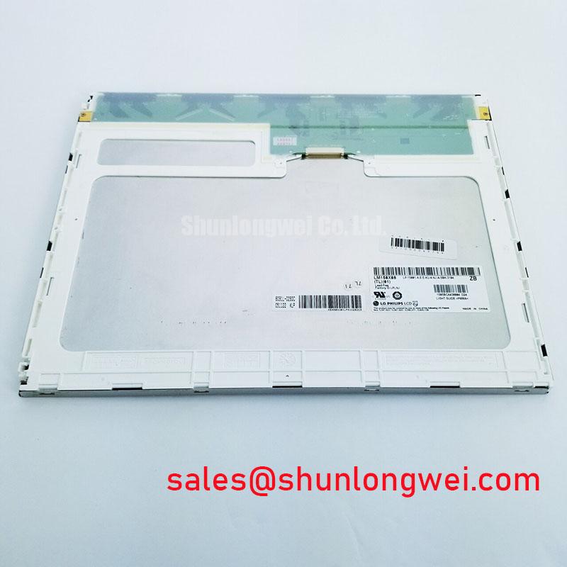
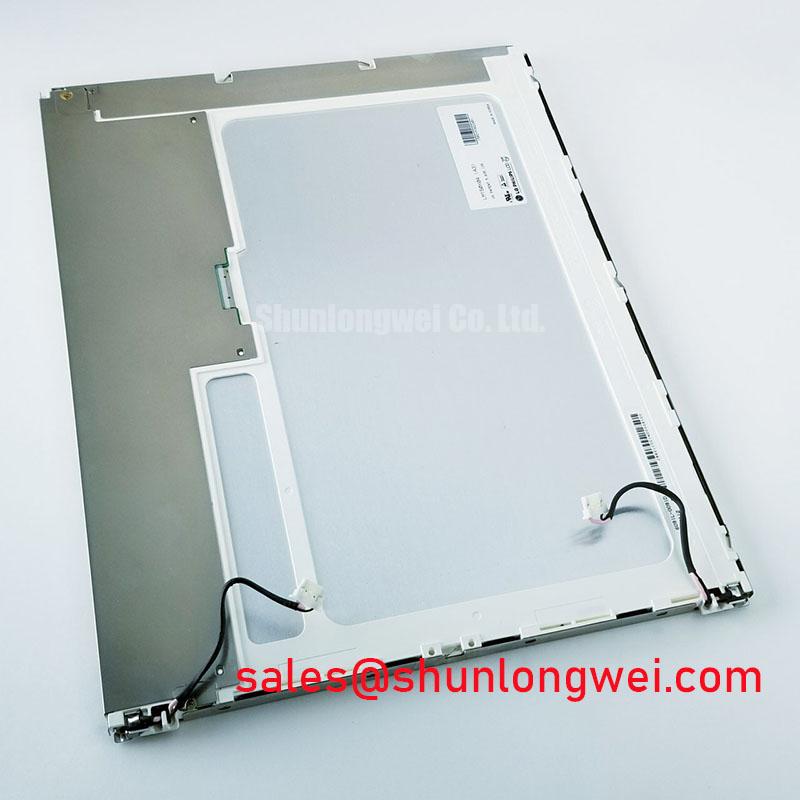
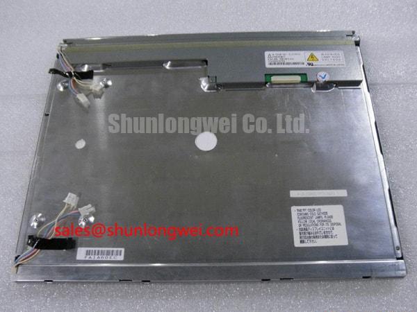
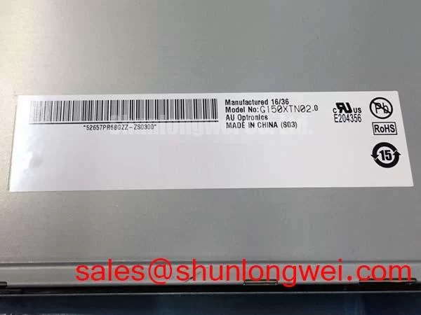
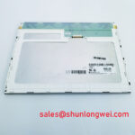
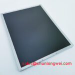
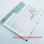
Start incoming inspection by confirming the label LM150X08-TL02, checking the TFT-LCD glass and bezel for visible damage, and recording the panel condition before applying power. The supplied factory information identifies this unit as an LG Display Industrial Grade LCD/HMI Panel in a TFT-LCD Display Module package, with its specification status recorded as Official Factory Spec Verified. The available product data does not confirm the panel resolution, active area, interface pinout, logic supply voltage, backlight type, luminance, viewing angle, or operating temperature. Those values must be checked against the original panel documentation and the equipment service record before installation.
For a replacement evaluation, treat the model marking as only one part of the identity check. Compare the connector position, mounting outline, cable orientation, controller compatibility, and backlight interface with the removed display. An apparently similar 15-inch industrial display can still fail to start correctly when its timing controller, data mapping, power sequence, or backlight driver requirements differ.
| Manufacturer | LG Display |
| Model | LM150X08-TL02 |
| Product category | Industrial Grade LCD/HMI Panel |
| Package or enclosure | TFT-LCD Display Module |
| Specification status | Official Factory Spec Verified |
Before connecting a replacement to a marine radar display, navigation bridge console, or another industrial HMI, the system integrator should verify the original panel documentation for the required supply voltage and signal standard. Do not assume that a connector with the same physical pitch carries the same pin assignment. Confirm ground references, enable lines, display timing, backlight control, and cable keying with the equipment schematic.
VESA vs. JEIDA Data Mapping Alignment and Even/Odd Channel Signal Integrity
Signal verification should begin at the host controller rather than at the glass alone. The LM150X08-TL02 product information supplied here does not identify whether its input uses JEIDA or VESA data mapping, nor does it confirm the number of LVDS channels or the required differential polarity. A replacement inspection therefore needs a known-good reference from the original system. Record the connector pin numbers, pair assignments, clock pair, ground pins, power pins, and control signals before removing the existing panel.
A mapping error can produce incorrect colors, unstable graphics, split-screen behavior, or a picture that appears to start while carrying corrupted pixel information. Even and odd data channels must be traced as a complete signal group. When the controller supports selectable JEIDA or VESA formatting, test both only when the panel documentation or the equipment design permits that adjustment. Do not select a mapping based on a visually similar connector or on a generic panel family assumption.
Design Consideration: High-speed differential routing should preserve a controlled, symmetrical transmission path, with the system designer verifying the intended characteristic impedance, return path, pair matching, and termination against the controller and cable specifications. The frequently used 100-ohm differential value is a system-level routing convention, not an official electrical parameter confirmed for this particular LG Display module. Cable replacement should therefore use the original assembly specification whenever available.
Power-on behavior deserves the same attention as data mapping. A white screen, intermittent image, or delayed start may involve the order and timing of logic power, reset, display enable, and backlight enable. The integration team should observe these signals with suitable instruments and compare them with the known-good unit. The supplied information does not verify a required rise-time window such as 0.5 ms to 10 ms for this model, so that range must not be treated as a factory limit.
Backlight dimming also requires documentation-based verification. If the host uses PWM, check that the controller’s frequency, duty-cycle behavior, enable polarity, and minimum operating duty are compatible with the panel and its driver. The suggested 200 Hz to 1 kHz range in a system design brief is not confirmed as an LM150X08-TL02 specification. Visual flicker, audible noise, or uneven brightness should be assessed with the actual backlight assembly and driver rather than corrected by changing the panel interface blindly.
For incoming QA, display a full-screen white, black, red, green, and blue sequence after the signal link is stable. Inspect the center, corners, and perimeter for stuck pixels, inactive areas, color contamination, or channel-related artifacts. Photograph the result under controlled lighting and retain the image with the serial and equipment records. A second test using fine text and vertical lines can expose mapping or timing problems that are difficult to see on a uniform color field.
High-Voltage Striking Potential and Secondary Coil Insulation Testing
The backlight architecture must be identified before any electrical test. The supplied factory data classifies the product as a TFT-LCD display module but does not confirm whether the specific assembly uses a CCFL backlight, an LED backlight, an integrated driver, or an external driver arrangement. The system integrator should verify the required backlight technology and voltage from the original panel documentation. A CCFL ignition circuit and a constant-current LED driver require different test instruments, isolation methods, and enable controls.
Where the original equipment uses a CCFL inverter, high-voltage ignition is a property of the inverter and lamp circuit, not a general rating that can be assigned to the LM150X08-TL02 without its official electrical sheet. The proposed 1500 to 1650 Vrms striking range must therefore be treated as an unconfirmed system test condition. Insulation checks should follow the equipment manufacturer’s service procedure and the applicable safety requirements for the assembled product. Use an appropriate high-voltage probe, controlled access, and a discharge procedure; never probe an energized backlight circuit with ordinary bench leads.
If the system has been converted to LED, confirm the current regulation method, feedback path, enable logic, and dimming interface. A stated 1000:1 PWM dimming ratio is not verified for this display module and should not be presented as a product capability. A backlight that turns on briefly and then shuts down may involve driver protection, an open lamp path, incorrect feedback, thermal behavior, or a control mismatch. Measure the driver output and control signals against the original assembly before assigning a cause.
Secondary-coil and cable insulation evaluation belongs to the complete inverter and harness assembly. The display module’s category alone does not establish a withstand voltage, creepage distance, clearance, or insulation resistance limit. Test conditions should be selected by the responsible safety engineer from the original equipment specification and relevant production procedure. High-voltage testing can damage sensitive display electronics when applied to the wrong terminals, so isolate the panel logic and data circuitry as required by the approved method.
High-EMI equipment also requires disciplined cable routing. Keep the high-speed data cable separated from inverter outputs and switching power loops where the mechanical design allows it, and preserve the original shield termination arrangement. Differential pair impedance and skew targets must be taken from the controller, cable, and panel interface documentation. Values such as 100 ohms with a 10 percent tolerance or a 50 ps skew budget are engineering targets sometimes used in system design, not confirmed factory specifications for this model.
During the bench test, run the backlight through its intended brightness range while monitoring image stability, connector temperature, and acoustic behavior. Test brightness changes while displaying fine text and gray ramps, because a control mismatch may be more visible in low-light scenes than on a bright white field. Do not infer a guaranteed half-life or MTBF from the product category. No field-life data or authoritative lifetime figure has been supplied for this page.
Surface Anti-Glare and Anti-Reflective Coating for High Ambient Readability
For a panel considered for a high-ambient navigation or radar console, inspect readability with the actual front surface, cover glass, viewing position, and enclosure lighting. The available factory information does not confirm an anti-glare treatment, anti-reflective treatment, optical bonding, surface hardness, haze value, or reflectance value for the LM150X08-TL02. These characteristics should be verified from the panel documentation or measured on the delivered assembly rather than inferred from the LG Display model designation.
A matte surface can reduce the visual sharpness of reflected light, while a glossy or untreated surface may preserve more apparent contrast but show stronger reflections. The correct choice depends on the cover window, ambient illumination, operator position, and required text size. For a marine bridge console exposed to daylight, evaluate the complete front stack under representative illumination. Salt residue, condensation, and a poorly sealed bezel can affect readability even when the LCD itself is functioning correctly.
Do not assume a particular liquid-crystal mode from this product record. TN, IPS, and MVA characteristics differ in viewing behavior, grayscale transitions, and off-axis contrast, but the supplied information does not identify the panel mode or confirm a symmetric 85-degree viewing specification. The acceptance test should measure the viewing positions that matter to the equipment operator and should document color shift, black-level change, and loss of fine detail across those positions.
Gray-scale testing is especially useful for identifying image quality changes that are not obvious on primary colors. Display a stepped gray pattern, low-contrast text, and moving test bars while viewing the panel from the intended operator angles. If a dark pattern appears to change tone with viewing position, compare it with the original panel under the same conditions. Avoid describing the result as a confirmed TN inversion or IPS advantage unless the panel technology is documented.
Temperature testing must also remain evidence-based. The supplied data does not verify a rated operating range of minus 20°C to minus 30°C, a cold-start response time, or a heater-strip requirement. If the equipment environment includes low temperatures, the system designer should evaluate startup, grayscale response, condensation control, and enclosure heating using the documented rating of the complete assembly. A warmer enclosure may improve liquid-crystal response, but it can also alter condensation behavior and thermal loading, so the control method must be validated at system level.
Brightness uniformity is best checked after the display has reached a stable operating condition. Use a consistent white test image and compare multiple areas of the visible field with the same measurement geometry. Uneven illumination can originate from the backlight, diffuser, optical stack, driver regulation, mechanical pressure, or enclosure reflections. The inspection should record the pattern rather than assign a single cause without additional evidence.
For background on display construction, interface selection, and common integration assumptions, engineers can consult The Ultimate Guide to Industrial TFT-LCD Display Technology while keeping the model-specific acceptance limits tied to the original documentation.
Flush-Mount Open-Frame Bezel Integration and Perimeter Gasket Shock Isolation
Mechanical inspection should compare the panel’s actual bezel envelope, mounting holes, connector clearance, cable bend path, and visible aperture with the equipment chassis. The supplied factory data does not include outer dimensions, mounting-hole coordinates, bezel tolerances, gasket material, or a confirmation that this module is an open-frame design. Measure the replacement and compare it with the removed unit before machining a flush-mount opening.
A flush installation should support the perimeter without pressing on the active display area. The gasket should provide environmental separation while allowing the enclosure and panel to accommodate normal assembly variation. Excessive local pressure can create visible nonuniformity, bezel stress, or image changes near the edge. These symptoms require inspection of the mounting interface, gasket compression, frame flatness, and cable routing; they should not automatically be attributed to an internal optical defect.
The proposed cross-pattern M3 fastener torque of 0.35 to 0.45 N·m is a general mechanical integration reference, not an official LM150X08-TL02 factory limit. Use the chassis and fastener manufacturer’s documented value, apply it evenly, and confirm that the panel frame is not distorted during tightening. A diagonal tightening sequence can help distribute load, but the final method remains dependent on the enclosure design and approved assembly procedure.
Bench Tip: Power down the equipment, discharge the backlight circuit, use ESD protection, and push the display cable fully flush before locking its connector.
After mechanical installation, repeat the full-field optical inspection. Check white and black screens for edge shading, localized bright areas, pressure marks, and changes caused by bezel tightening. Then display fine text and moving graphics while gently observing the cable route and connector retention without applying force to the glass. Any intermittent image should be investigated through connector seating, cable continuity, power sequencing, grounding, and controller output comparisons.
For a harsh marine radar or navigation bridge console, enclosure sealing and corrosion control must be evaluated at the equipment level. The product record supplied here does not certify salt-fog resistance, ingress protection, shock qualification, vibration performance, optical bonding, or long-term moisture resistance for this module. The integrator should verify those requirements for the complete display assembly, including the front window, gasket, rear cover, cable exits, and service access points.
Thermal design should preserve airflow or heat transfer paths identified by the original equipment construction. Avoid placing heat-generating driver components directly against the panel frame unless the approved mechanical design permits it. During a prolonged functional test, check the image for brightness drift and inspect the enclosure for localized heating. Any thermal limit, lifetime expectation, or reliability claim must come from the applicable LG Display documentation or a qualified system test report.
The LM150X08-TL02 is therefore best evaluated as an LG Display TFT-LCD display module whose confirmed product category and model identity support a structured replacement inspection. Electrical compatibility, backlight architecture, optical treatment, environmental capability, and mechanical fit remain documentation and system verification items before procurement approval or field installation.