

Content last revised on October 16, 2026
Normally White TN Grayscale Inversion Mitigation & Optimal Viewing Direction Alignment
Display a grayscale ramp and inspect it from the operator’s actual viewing position before adjusting brightness or changing controller settings. Design Consideration: TN grayscale inversion is an angle-dependent optical effect; it should be distinguished from incorrect gamma settings, unstable video timing, and pressure-related background variation. Treat normally white operation and TN construction as characteristics requiring confirmation for the installed panel revision, rather than inferring them from the model name.
Move the observation point vertically and horizontally while keeping the test image and ambient lighting unchanged. A tonal reversal that follows viewing direction calls for an orientation assessment. A grayscale error that remains visible from every position instead warrants examination of the source image, controller configuration, and accessible timing-controller circuitry. IPS and MVA viewing behavior provides useful comparison context, but symmetric viewing-angle figures cannot be transferred to this module.
Surface reflections also influence apparent contrast. Evaluate the assembled display with its protective window fitted, because window spacing, contamination, and incident light can change readability. Anti-glare surface treatment scatters reflections; it does not independently establish sunlight readability. The explanation of Amorphous Silicon (a-Si) TFT Technology provides background on active matrix switching without establishing the semiconductor construction of this particular panel.
For unstable grayscale transitions, compare the controller output timing with the receiver requirements across the equipment’s specified temperature range. TTL timing analysis concerns single-ended logic thresholds and setup and hold requirements; LVDS analysis concerns differential signaling and clock relationships. Identify the installed interface before selecting either measurement method. Probe loading and measurement location should be included when judging clock jitter and remaining timing margin.
VESA vs. JEIDA Data Mapping Alignment & Even/Odd Channel Signal Integrity
Trace the controller’s color-bit assignment to the panel connector before changing VESA or JEIDA mapping options. Design Consideration: a mapping mismatch can alter color significance, while channel-order or timing errors can produce spatial image defects. Use color ramps, fine vertical patterns, and a stable reference image to separate these possibilities; a split image alone does not identify the defective part.
Check the logic supply at the panel connector during startup, including its rise behavior and relationship to video enable and backlight enable. Apply the panel’s specified sequencing limits rather than importing timing values from another display. For an LVDS interface, 100 Ω differential impedance is a common engineering reference, not an independently established AA150XN07 specification. Cable construction, connector transitions, and the transmitter and receiver requirements determine the implemented interconnect.
The VESA Video Electronics Standards Association Official Portal provides standards context, but connector similarity does not establish a particular mapping or replacement relationship. When evaluating AA150XN03 alongside AA150XN07, use the following comparison to organize the interchangeability check.
| Selection checkpoint | AA150XN07 | AA150XN03 comparison requirement |
|---|---|---|
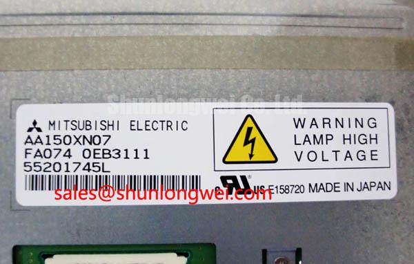
| Product identity | Mitsubishi Electric TFT-LCD active matrix color display module | Confirm complete manufacturer identification and revision |
| Electrical and optical specifications | Consult Datasheet | Compare resolution, supply, interface, mapping, viewing direction, and backlight requirements |
| Mechanical interchangeability | Retain the installed assembly as the dimensional reference | Compare outline, mounting points, connector position, and bezel clearance |
| Replacement decision | Reference model for this assessment | Establish compatibility through documented comparison and equipment testing |
For a high-voltage substation protection terminal or SCADA dispatch console, designers should verify alarm-color rendering, text legibility, and startup behavior with the actual controller. Backlight assessment should distinguish brightness depreciation from outright failure: a brightness-maintenance endpoint is not interchangeable with MTBF. Examine driver output stability, connector condition, and thermal distribution without assigning an unsupported service-life figure.
Shielded FFC/FPC Flat Flexible Cable Grounding across 360-Degree Connector Shells
Inspect the existing display cable’s shielding and chassis termination before adding suppression components. Design Consideration: where a shielded cable and conductive connector shell are present, circumferential shield contact can reduce discontinuities in the high-frequency return path. A bare flexible cable requires a different integration assessment; neither construction should be assumed from the AA150XN07 designation.
When pixel disturbance coincides with nearby drive switching, compare the image and receiver waveforms under repeatable operating conditions. Check cable routing relative to switching conductors, chassis bonding, connector retention, and supply disturbance. Common-mode suppression should follow measured interference behavior and subsequent signal-integrity verification. It cannot guarantee removal of horizontal bands, and component-level changes do not establish equipment EMC compliance.
Keep display power, video signaling, and backlight power paths distinct when reviewing the schematic. The TX17D02VM2CAA-2 is a separate display reference for broader system comparisons; its inclusion does not establish that it is a backlight driver, companion circuit, or electrically compatible part for AA150XN07.
Evaluate readability under the intended enclosure lighting while monitoring panel temperature. Bright ambient illumination changes perceived contrast, so dark-room contrast figures cannot establish performance under direct sunlight. Check gasket compression and mounting contact for uneven loading, which can contribute to localized nonuniformity. Maintenance Note: Inspect cooling passages and gasket seating periodically so accumulated dust and displaced seals do not compromise heat removal or apply uneven pressure to the display assembly.
Full-Screen Primary Color AOI Screening: Stuck Sub-Pixels & Background Uniformity Audit
Run a bench sequence of full-screen red, green, and blue images, followed by neutral fields, with the controller held at its intended output settings. Engineering Recommendation: record persistent bright or dark points, line defects, flicker, and background variation using consistent viewing conditions. Apply the agreed inspection criteria rather than inventing a universal pixel-defect acceptance threshold.
Compare a neutral field before and after mounting to identify changes associated with bezel contact or fastening stress. If a faint image remains visible under oblique external illumination while internal illumination is absent, investigate the backlight supply and enable path. This observation helps separate diagnostic paths; it does not establish a particular internal driver fracture or backlight failure by itself.
When grayscale errors remain, examine accessible timing-controller supply and gamma-reference measurements against service information or a known-good assembly. Avoid adjusting reference voltages to conceal a defect before checking video levels and connections. The Ultimate Guide to Industrial TFT LCD Technology offers broader context for interpreting display behavior during this assessment.
At low temperature, liquid-crystal response can slow and moving transitions can smear. Test within the documented operating envelope and allow a cold assembly to acclimatize before energizing it where condensation is possible. Any enclosure heating requires system-level temperature control and validation. Repeat the image inspection after thermal stabilization to distinguish persistent defects from temperature-dependent response and moisture-related behavior.