Content last revised on September 11, 2026
Preventing Frame Lag & Image Smearing in Cryogenic Storage & Outdoor Industrial Facilities
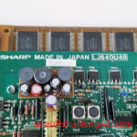
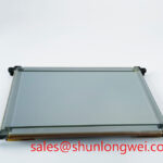
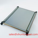
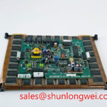
With the equipment isolated from power, inspect the LJ640U48 module’s TFT LCD viewing area, perimeter frame, connector seating, gasket contact surfaces, and chassis support points before it is returned to service. This Sharp unit is identified as an Industrial Grade LCD/HMI Panel in a TFT LCD Display Module enclosure. The supplied product record does not confirm the panel interface, logic supply requirement, backlight arrangement, timing values, optical ratings, or environmental operating limits.
That verification step matters when a display is being assessed for an industrial control terminal, an AGV operator interface, or a forklift telematics screen. A panel can fit mechanically while still requiring different electrical signaling, power sequencing, firmware configuration, or mounting geometry. The module part number should therefore be matched against the removed assembly and the host controller documentation before any replacement decision is made.
When the LJ640U48 Sharp TFT LCD Display Module is evaluated for use in cold stores, outdoor cabinets, AGV terminals, or forklift displays, screen behavior should be checked at the actual enclosure temperature rather than only at room temperature. Liquid crystal response can slow at low ambient temperature, which can be seen as delayed transitions, motion trailing, or incomplete updates on changing dark and gray image areas. This is a general Design Consideration, not an official response time or temperature rating for this model.
A practical inspection begins with a stable test image containing gray ramps, moving text, dark fields, and alternating light patterns. Compare the result with a known good host display path where possible. If smearing appears only after the equipment has been parked in a cold area, engineers should check the cabinet’s thermal condition, condensation control, cable strain relief, and connector retention before attributing the behavior to the LCD module itself. Moisture around a connector or enclosure seal can affect the wider display assembly and should be addressed through the machine maintenance procedure.
The supplied factory data does not establish an operating range from −30°C to +85°C, nor does it specify liquid crystal response behavior across thermal cycles. System integrators should verify the approved temperature range and any heater control requirements from the original Sharp documentation and the equipment maker’s service manual. Perimeter seal condition can be visually reviewed for lifting, contamination, or uneven compression, but no material composition or sealing performance should be assumed from the module category alone.
For installations using high speed differential display signaling, controlled impedance and pair to pair timing are system level concerns. Routing around motor drives, radio equipment, contactors, and inverter cables should minimize electromagnetic coupling and preserve the signal path intended by the host controller. A 100 Ω differential route with a ±10% tolerance and a 50 ps skew budget are common interface design targets for applicable differential links, but they are not confirmed requirements of the LJ640U48. The system engineer should confirm the actual interface standard before applying those values.
Industrial display integration practices are discussed by Sharp Devices Europe Industrial Display Solutions. For field technicians, the useful question is whether the observed image issue follows the panel, the cable, the display controller, or the local temperature condition. Swapping only one variable at a time gives a more reliable service record than assigning a single cause from the visible symptom.
Preventing Localized Optical Compression and Brightness Nonuniformity on Dark Screen Fields
Inspect the support plane behind the LJ640U48 before tightening the surrounding bezel. Dark screen fields are useful during this check because uneven mechanical loading can become visible as local brightness variation, pressure marks, or optical nonuniformity. Such effects may arise from a distorted chassis, trapped cable, debris under a support edge, or fasteners tightened unevenly. They should not be interpreted as proof of a particular internal structure because the supplied factory record does not define the panel’s internal optical stack.
The mounting surface should be clean, flat within the original equipment manufacturer’s tolerance, and free from hardware that applies point loading to the display. Confirm that the module is supported only at intended mounting locations and that the bezel does not press into the active viewing region. If a machine uses a dust gasket, examine whether the gasket has taken a permanent set, shifted during installation, or collected particles that prevent uniform contact. Proper gasket contact supports enclosure protection and avoids concentrating mechanical stress at one part of the frame.
⚠️ Maintenance Note: Tighten display mounting hardware gradually in a cross pattern and use only the torque specified by the original equipment documentation to avoid uneven frame stress.
The requested M3 torque range of 0.35–0.45 N·m is a general mounting reference only and is not an official LJ640U48 specification in the supplied data. Fastener torque must be determined by the complete assembly, including the chassis material, screw type, bracket design, washers, gasket thickness, and the equipment manufacturer’s instructions. Applying a generic torque value without those conditions can damage the mounting system or cause uneven loading.
Cold temperature can also alter the visible response of an LCD, so evaluate dark field appearance after the display and its enclosure have stabilized at the intended site condition. If an enclosure includes a heater strip, its controller, sensor placement, wiring, and safe operating sequence belong to the host system design. The LJ640U48 product record does not verify the presence of an integral heater or define a heater control scheme. Designers should validate that any external thermal management method does not introduce hot spots, trapped moisture, or localized frame loading.
When a replacement candidate is being considered, physical dimensions, visible area, mounting points, connector position, electrical interface, and firmware mapping all require comparison. The LM057QC1T08 can be reviewed as a separately listed display module for replacement evaluation, but compatibility must be verified against the original panel documentation and the host equipment design. A similar format or resolution class alone does not establish direct interchangeability.
Backlight Driving, Dimming & Flicker Suppression
The supplied official record identifies the LJ640U48 as a Sharp industrial TFT LCD/HMI panel, but it does not state whether its illumination uses WLED, CCFL, or another backlight configuration. It also does not provide backlight voltage, current, ignition behavior, dimming method, brightness, lifetime, or flicker performance. For this reason, a service team should not connect a generic LED driver or a CCFL inverter based only on the module category.
Before reconnecting a display assembly, trace the original backlight supply from the machine schematic and inspect the mating connector, harness condition, driver board markings, and controller enable path. If a screen is visible under external illumination but lacks its normal illumination, the fault may be in the backlight circuit, interconnect, host power rail, controller enable logic, or panel assembly. Scope measurements should be compared with a known good signal path and interpreted according to the original equipment documentation.
Constant current regulation is generally important for LED backlight systems because it manages current through the light source. PWM control is commonly used in display systems for brightness adjustment, but a claimed 1000:1 dimming ratio is not confirmed for the LJ640U48. Likewise, high voltage CCFL cold ignition figures and a 50,000 hour brightness life value are not official specifications supplied for this model. Those properties must be verified from the correct panel datasheet and original driver documentation.
Acoustic noise, visible flicker, and brightness instability can be assessed without inventing a failure threshold. Listen for changes during brightness commands, inspect the driver board for mechanical looseness, and observe the display with a camera or instrument suitable for the investigation. Results should be correlated with supply stability, ambient temperature, controller configuration, and the display content being shown. A dimming artifact can be produced by multiple sections of the assembly, so evidence from the actual equipment should guide the repair action.
For a wider explanation of industrial LCD integration, environmental evaluation, and interface selection practices, technicians can consult The Ultimate Guide to Industrial TFT LCD Technology. It is useful as a maintenance reference, while the original LJ640U48 documentation remains the authority for model specific electrical and optical requirements.
VESA vs. JEIDA Data Mapping Alignment & Even/Odd Channel Signal Integrity
Before applying power to the LJ640U48, confirm connector orientation, pin assignment, logic supply requirement, and panel timing from the original panel documentation. The supplied product data does not identify a 3.3 V or 5.0 V logic supply, does not state the power on rise time, and does not confirm whether VESA or JEIDA mapping applies. These parameters cannot be safely inferred from the display size, TFT technology, or industrial HMI classification.
Incorrect mapping or mismatched color bit order can present as abnormal colors, split image regions, missing tones, or unstable picture content. These symptoms can also arise from a damaged cable, poor connector engagement, controller configuration, or timing incompatibility. The service approach should be to inspect the cable and connector first, compare host settings with the removed panel’s documented requirements, and test against an approved known good display path where available.
Even and odd channel integrity is relevant only when the confirmed interface architecture uses those channels. If the equipment uses differential signaling, preserve matched routing and avoid routing sensitive display conductors alongside high current switching paths where possible. Cable length, shielding termination, chassis bonding, and connector retention are determined by the complete machine. Engineers should verify peak signal quality at the panel connector during system testing rather than relying on a generic routing number.
Power sequencing deserves the same discipline. Applying data before supplies are stable, disconnecting cables while energized, or bypassing the host controller’s sequence can place unnecessary stress on the display system. The cited 0.5 ms to 10 ms rise time window is not an official LJ640U48 requirement and should not be used as a repair instruction. Follow the panel and host controller documentation for the permitted order of logic power, interface data, and illumination enable signals.
For a telematics terminal in an AGV or heavy duty forklift, assess vibration restraint, connector locking, dust sealing, and condensation exposure as part of the complete display installation. A separately listed LQ150X1LG11 display module can be considered when reviewing broader display subsystem options, but it is not evidence of electrical or mechanical equivalence to the LJ640U48. Where an installation is exposed to unusual radiation environments, the general concept of single event effects may be relevant to electronic systems, yet no cosmic ray or latchup performance claim is made for this LCD module.