


Content last revised on September 10, 2026
Full-Screen Primary Color AOI Screening: Stuck Sub-Pixels and Background Uniformity Audit
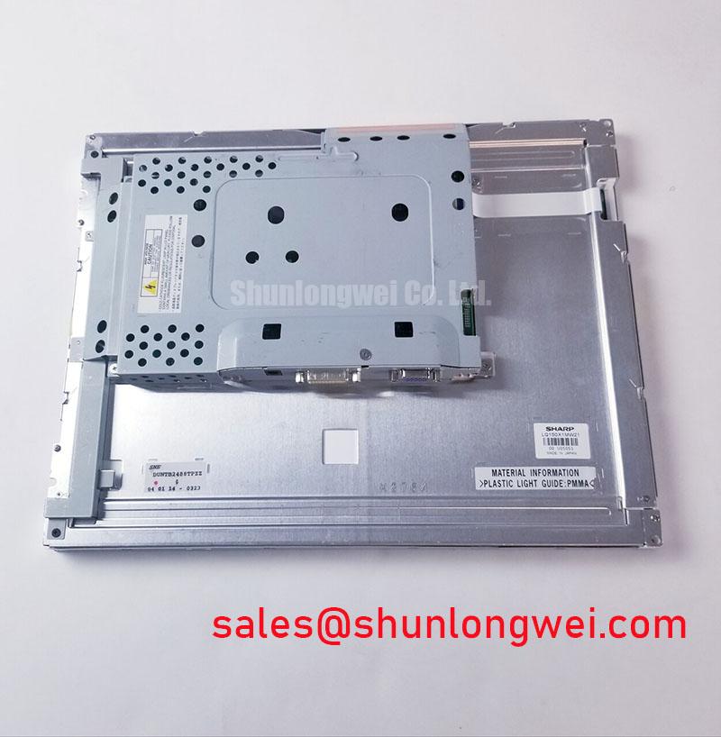
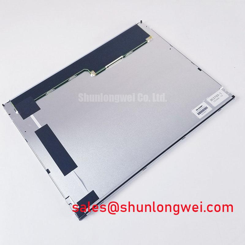
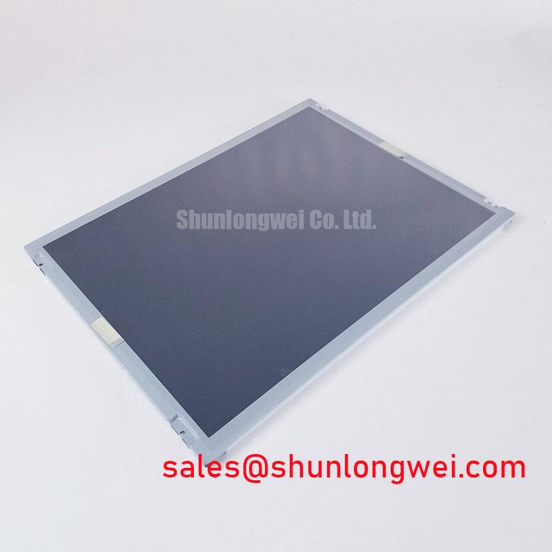
Begin the incoming inspection by checking the LQ150X1LG11 label against the equipment service record, then examine the TFT-LCD module for cracked glass, frame distortion, connector damage, and visible contamination before applying power. Sharp is identified as the manufacturer, and the product is classified as an Industrial Grade LCD/HMI Panel in a TFT-LCD Display Module package. The supplied factory information confirms the product category and manufacturer, but it does not provide a complete electrical pinout, optical table, backlight rating, dimensional drawing, or interface timing sheet. Those items should be verified against the original panel documentation before installation.
This distinction matters when the display is being sourced for a high-precision surgical navigation console, ultrasound diagnostic display, industrial HMI, or monitoring panel. A visually similar panel can still fail at the mechanical interface, data mapping, power sequence, or backlight control stage. The correct replacement assessment therefore starts with the original system documentation and the installed cable assembly rather than with screen size alone.
| Item | Verified information | Integration implication |
|---|---|---|
| Model | LQ150X1LG11 | Use the complete part marking when matching service records and procurement documents. |
| Manufacturer | Sharp | Confirm that the host equipment documentation identifies the same manufacturer and model family. |
| Product category | Industrial Grade LCD/HMI Panel | Suitable for engineering evaluation in industrial display assemblies, subject to system validation. |
| Package | TFT-LCD Display Module | Mechanical frame, connector position, bezel opening, and controller compatibility require inspection. |
| Specification status | Limited factory information available | Only the listed factory information should be treated as confirmed in this product record. |
Full-Screen Primary Color AOI Screening: Stuck Sub-Pixels and Background Uniformity Audit
After the visual inspection, connect the panel only through a known-compatible host interface and display full-screen red, green, blue, white, black, and neutral-gray test fields. Record any fixed bright point, dark point, vertical line, horizontal band, corner shading, or region that changes appearance when the display cable is gently stabilized. This is a bench-screening procedure, not a manufacturer acceptance limit, because the available product information does not state a pixel-defect class or uniformity tolerance for this model.
A useful three-stage sequence is to check the complete field at normal viewing distance, inspect suspected areas under controlled ambient lighting, and then repeat the test with alternate image content. A point that remains fixed across primary colors may require pixel-defect evaluation. A broad variation that follows the image field, changes with viewing angle, or appears mainly in dark scenes should be recorded separately from a narrow electronic line defect. The service record should include the input condition, displayed test field, ambient temperature, and photographs taken perpendicular to the panel.
A 45-degree flashlight inspection can help separate an external surface or illumination issue from an active image-path problem. With the panel unpowered, sweep the light across the cover and bezel while looking for scratches, pressure marks, foreign particles, or localized shadowing. With the panel operating, compare the suspected area on black and white fields without pressing the glass. This method can expose a mechanical obstruction or illumination nonuniformity, but it cannot prove a specific internal failure mechanism. Any line defect should be checked against the connector seating, cable retention, controller output, and a known-good signal path.
For equipment that may be evaluated in low-temperature rooms, do not assume that a slow visual response indicates permanent damage. Liquid-crystal response can change with temperature, and the displayed transition may appear elongated during a cold start. Designers should verify the panel’s documented operating temperature range and warm-up requirements from the original Sharp documentation. If a heater strip is part of the host enclosure, its control should be assessed as a system function, with attention to local temperature gradients, condensation control, and the display manufacturer’s limits. The heater must not be allowed to create direct hot spots against the panel edge.
Touch operation is also a system-level matter. The available factory data identifies this item as a TFT-LCD display module and does not confirm an integrated resistive or capacitive touch layer. For a surgical navigation or ultrasound console, the integrator should verify whether touch sensing is provided by a separate overlay, a front-panel controller, or an external input device. Gloved operation and operation with moisture on the surface should be tested on the complete assembly, because sensitivity depends on the touch controller, cover stack, grounding, firmware, and enclosure design rather than on the LCD module alone.
Eye-Diagram Voltage Margin and Differential Noise-Floor Verification in High-Vibration Bays
When the display is installed near variable-frequency motor drives, servo amplifiers, switching power supplies, or long cable harnesses, begin troubleshooting at the signal source and compare it with the panel-side waveform. A blank screen, intermittent image, or horizontal noise band can involve power integrity, grounding, cable movement, connector contact, data-format mismatch, or electromagnetic coupling. It should not be assigned to one cause without measurement.
The LQ150X1LG11 product record does not confirm whether the module uses LVDS, TTL, a particular connector count, or a specified differential voltage range. The system integrator should verify the required interface from the original panel documentation and controller board. If the host uses LVDS, inspect the complete differential route, including connector pin assignment, pair polarity, termination arrangement, shield bonding, and return-current path. If the host uses TTL, the voltage thresholds, clock relationship, cable length, and ground reference must be checked separately. Do not connect an unverified transmitter to the panel solely because the connector appears mechanically similar.
A shielded cable can reduce electric-field coupling, but its termination must match the equipment grounding strategy. In a vibrating bay, inspect shield continuity and strain relief while the system is unpowered, then observe the image during controlled cable movement without exceeding the connector’s mechanical limits. Ferrite components may be considered where conducted or radiated interference has been demonstrated, but their impedance behavior must be evaluated across the relevant frequency range. Adding a ferrite without checking the signal waveform can alter edge shape or common-mode behavior.
For a differential link, use an appropriate probe arrangement and compare the eye opening, crossing behavior, common-mode movement, and clock-to-data relationship with the controller’s known-good output. The available factory information does not define an eye-mask limit, jitter allowance, or data hold-time specification for this model. Those values must come from the original Sharp panel documentation or the selected controller. Temperature testing should cover the actual equipment operating window, because oscillator drift, driver timing, cable loss, and liquid-crystal response can all change with temperature.
💡 Pro Tip: Disconnect power before reseating the display cable, and use controlled differential probing rather than attaching a long ground lead that can introduce false noise into the measurement.
For a potential high-precision medical display application, image stability should be validated with the complete enclosure, cable routing, power supply, and nearby equipment operating in its normal switching state. The panel itself cannot independently establish compliance with CISPR, EN 55011, or any complete-system EMC requirement. EMC performance belongs to the assembled equipment and its verified installation conditions.
Interface Pinout, Timing, Pixel Clock, and Skew Compensation
Connector count is not a specification. A 20-pin or 30-pin connector may carry different functions across manufacturers and model families, so the LQ150X1LG11 should be matched by its documented pinout and electrical interface rather than by connector appearance. Before powering a replacement, trace the host cable from the controller to the panel, identify the logic supply, grounds, enable signals, clock pair, data pairs, and any backlight control connections, and compare them with the original documentation.
The provided product data does not confirm a logic supply voltage of 3.3 V or 5.0 V for this model. The system integrator should verify the required supply voltage from the original panel documentation. The same rule applies to backlight supply, dimming method, enable polarity, protection functions, and connector orientation. Do not combine an unconfirmed panel with a controller that offers selectable voltage simply because both options are available on the controller board.
If the documented interface is LVDS, differential routing should preserve pair identity and polarity, maintain a controlled transmission environment, and minimize unnecessary stubs. A commonly used differential design target is 100 ohms, but the final routing requirement must follow the controller, cable, and panel documentation. Designers should verify impedance with the selected stackup and cable construction, then check the actual clock and data waveform at the panel connector. Excessive skew can produce split-screen artifacts, unstable color fields, misplaced columns, or intermittent synchronization, yet similar symptoms can also arise from incorrect JEIDA or VESA mapping.
JEIDA and VESA data formats should therefore be confirmed from the original panel specification and controller configuration. Bit-order settings, color depth, lane assignment, clock polarity, and synchronization behavior must agree at both ends. A panel that powers up with a white field is not necessarily correctly configured; the backlight can operate while the image data remains invalid. When the picture is divided, shifted, or limited to a portion of the screen, compare the controller mapping, lane continuity, clock quality, and panel enable timing before changing hardware.
Power sequencing must be evaluated as a host-system requirement. The supplied information does not confirm the requested rise-time window of 0.5 ms to 10 ms for this model, so that interval must not be treated as an LQ150X1LG11 factory specification. Measure the logic rail, display enable, video clock, and backlight control during startup and shutdown, then compare the captured sequence with the original equipment behavior and the panel documentation. The purpose is to prevent undefined states and abnormal stress while allowing the system designer to determine acceptable timing margins through testing.
For sourcing decisions, the LMS700KF01-001 may be reviewed as a separately documented display option during a same-size or same-resolution replacement assessment. It should not be treated as a drop-in substitute until its active area, mounting geometry, optical characteristics, connector, interface timing, supply requirements, and backlight control have been compared with the installed unit.
Suppressing Localized Thermal Gradients to Prevent Chronic Optical Yellowing and Color Shift
Thermal validation should start with the assembled display, not with the bare module. Install the panel in the intended bezel or housing, operate the controller and backlight under representative conditions, and map the front and rear surface temperatures after the enclosure reaches a stable state. The purpose is to locate persistent hot spots near narrow edges, driver electronics, power components, vents, or heater elements. The available factory information does not state an LED lifetime value, L70 or B50 rating, optical material composition, or allowable thermal gradient for the LQ150X1LG11, so those claims require the applicable manufacturer documentation.
An aluminum heat-spreader rail can be considered when enclosure measurements show a localized thermal concentration. Its position, contact method, electrical isolation, mechanical pressure, and airflow interaction should be determined by the system designer. A spreader that touches the active display area, distorts the frame, blocks a ventilation path, or transfers heat from a power component into the panel can create a new failure condition. Thermal interface materials should be applied only where the mechanical drawing and service procedure permit them; the correct thickness and compression are system-dependent.
Color shift should be assessed with repeatable image fields and a consistent measurement setup. Record white balance, primary-color appearance, gray-scale transitions, and luminance at several locations after cold start and after stabilized operation. A yellow or warm region may involve illumination aging, temperature distribution, optical stack behavior, controller settings, or measurement geometry. It should be correlated with temperature and operating history rather than attributed to a particular internal material or layer without documentary evidence.
Potential integration with a high-precision surgical navigation display or ultrasound diagnostic terminal requires additional system validation. Designers should verify luminance stability, grayscale rendering, viewing-angle requirements, enclosure sealing, cleaning compatibility, touch-overlay behavior, and the host system’s regulatory obligations. The LCD module does not independently provide medical-device approval or complete equipment safety certification. Procurement teams should also retain the exact model marking, interface documentation, dimensional drawing, and acceptance records for each approved configuration.
Where the display is paired with a separate controller or backlight solution, the LQ9D03B can be examined as a separately documented complementary display solution. Compatibility still depends on the actual electrical and mechanical interface. For broader engineering reference during fault isolation, The Ultimate Guide to Industrial TFT LCD Technology provides background for reviewing TFT interface principles, selection factors, and common integration assumptions.