

Content last revised on October 18, 2026
Backlight Driving, Dimming & Flicker Suppression Considerations
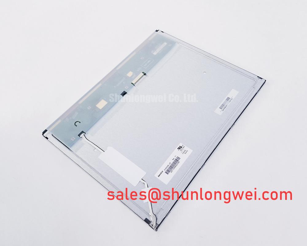
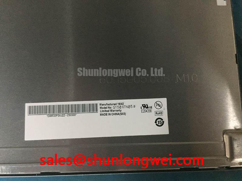
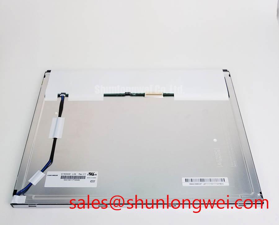
At a failed AGV or forklift display, isolate the panel from the host controller, inspect the display connector for uneven insertion, and compare the supply and signal conditions with the original equipment documentation before applying power. The G150XGE-L04 is identified here as an AUO industrial-grade TFT-LCD active matrix color display module in a standard form factor. Its supplied product identity does not establish a universal backlight voltage, interface pinout, touch technology, viewing-angle class, or optical coating, so replacement work should begin with a direct comparison against the removed panel and the equipment service drawing.
Backlight troubleshooting should separate the display image path from the illumination path. A black screen with a visible image under a controlled inspection light points the technician toward the backlight driver, enable signal, cable connection, or protection response rather than automatically indicating a defective LCD cell. A completely inactive image requires a separate check of the host output, panel supply path, timing signals, and connector seating.
The supplied data for the G150XGE-L04 does not confirm a WLED architecture, a constant-current driver, a 1000:1 PWM dimming ratio, a CCFL ignition requirement, or a 50,000-hour half-life rating. Those values must not be assigned to this model without the matching AUO panel documentation. When the original machine uses an external LED driver, the service engineer should record its output behavior during startup and dimming, then verify that the driver enable and fault lines follow the equipment controller sequence. If the original assembly uses another backlight technology, the replacement must be evaluated as a complete electrical interface rather than by appearance alone.
For a display installed in an AGV or forklift telematics console, brightness control can interact with the vehicle controller, camera overlay, and low-voltage power distribution. A PWM waveform that is acceptable to the driver may still produce visible modulation through a camera or produce switching noise in an adjacent sensor circuit. Use the original controller settings as the reference and check brightness transitions with the display connected to its intended driver. The Winstar industrial TFT-LCD and OLED reference is useful for comparing general module interface conventions, but it does not define the AUO model’s electrical limits.
LVDS or TTL timing should also be treated as system-interface information, not inferred from the model number. Confirm the transmitter type, clock polarity, lane arrangement, pixel order, and power sequencing from the original panel documentation. During a temperature-chamber or extended bench test, monitor the image for intermittent lines, frame tearing, or loss of synchronization while checking the source clock and data stability. The correct timing margin is determined by the matched transmitter, cable, receiver, and operating condition.
Radiated Emissions and Grounding Considerations
When a display is mounted near a variable-frequency drive or servo motor cable, pixel jitter and horizontal noise bands should be investigated as a complete cable and enclosure problem. The G150XGE-L04 listing does not certify the finished equipment to CISPR Class A or Class B, and an LCD module cannot independently claim system EMC compliance. The practical task is to identify how interference enters the signal reference, power return, or cable shield.
Begin by comparing the display with the motor drive disabled and enabled under the same image pattern. A change in noise synchronized with switching activity may indicate coupling through the harness, grounding arrangement, power converter, or signal reference. Inspect the full cable route, especially parallel runs with motor phases, brake wiring, and high-current DC links. The cable shield termination and enclosure bonding should be evaluated according to the system EMC plan rather than altered randomly at the panel connector.
A 360-degree shield termination can reduce high-frequency current spreading when the enclosure and cable construction support it, but the effectiveness depends on contact continuity, mounting pressure, paint or anodizing at the bonding point, and the return-current path. A star-ground arrangement may be useful as a design consideration where the backplate, controller, and display frame require a controlled reference. It is not an AUO factory specification for this model. Common-mode ferrite components are also system-level options, and their selection should follow measured interference behavior rather than being treated as a standard accessory.
For LVDS installations, route the differential pairs with consistent geometry and keep their reference plane continuous through the transition from controller to display. The system designer should verify pair polarity, lane mapping, termination, skew, and clock stability using the known-good signal path. If the module uses TTL rather than LVDS, apply the corresponding single-ended signal integrity rules instead of assuming that an LVDS remedy will transfer directly. The Industrial Display & HMI Solutions resource provides broader enclosure, grounding, and industrial integration context.
⚠️ Field Alert: Disconnect equipment power and allow the power rails to discharge before inserting or removing the display cable, because live connector handling can expose signal and supply pins to damaging transients.
Surface Treatment and Ambient Readability Considerations
Readability in a warehouse or outdoor vehicle cabin depends on the panel surface, cover lens, viewing direction, ambient reflections, brightness control, and enclosure geometry. The supplied baseline for the G150XGE-L04 identifies an active matrix color display module but does not confirm AG treatment, AR treatment, a specific viewing-angle figure, TN, IPS, or MVA construction. Those characteristics should be checked against the exact panel documentation and the removed unit.
During replacement evaluation, compare the display at the operator’s actual eye position rather than only at the workbench. Tilt the console through its normal adjustment range and inspect dark gray, warning red, and fine text patterns under direct overhead and side illumination. A reflective cover window can dominate the visual result even when the panel surface itself has an anti-glare treatment. Excessive surface diffusion may reduce mirror reflections while softening small characters, so optical performance should be judged with the complete front assembly.
Viewing-angle behavior also requires a controlled comparison. Grayscale inversion, color shift, or loss of contrast at an oblique angle can arise from the panel technology, the polarizer configuration, the cover lens, or the display settings. The general discussion of LCD viewing-angle characteristics can help technicians interpret these effects, but it does not establish a specification for the AUO part.
For a rugged telematics display, engineers should also verify whether the equipment uses a resistive or capacitive touch overlay. Touch response through gloves, moisture tolerance, cover-lens thickness, and controller compatibility belong to the assembled HMI, not automatically to the LCD module. If the replacement panel changes the optical stack or connector arrangement, validate touch accuracy and menu readability at the same time as image quality.
Heat Spreader Sizing and Thermal Interface Considerations
Thermal work around a replacement display starts with the enclosure, backlight driver, controller board, and air path. The G150XGE-L04 product identity supplied here does not specify an aluminum spreader, PMMA light guide, LED L70 or B50 life value, allowable case temperature, or internal thermal construction. These items should not be presented as factory features of this model.
Inspect the original mounting frame for contact pads, pressure points, insulating films, and clearance around the display edges. A heat spreader added by the equipment builder must not press against the active viewing area or distort the panel frame. Thermal interface material should cover the intended contact area without entering the connector region, flex cable path, or optical opening. The mechanical stack should be checked after tightening because uneven pressure can create localized image defects or make a marginal connector appear intermittent.
Use temperature measurements at the display frame, driver location, enclosure air, and nearby power components while the equipment operates through its real brightness and communication load. If a hot spot follows the external driver rather than the panel edge, improving the driver’s heat path may be more effective than adding metal to the LCD frame. If brightness falls or image stability changes as the enclosure warms, compare the timing signals and supply rails at the same time; temperature can affect several parts of the system simultaneously.
Designers evaluating the G150XGE-L04 for CNC operator panels, industrial HMI consoles, AGV displays, or forklift telematics should confirm the mechanical envelope, connector orientation, optical stack, backlight interface, and touch arrangement before committing to a field replacement. The neutral same-size and same-resolution comparison point LQ150X1DWF1 may also be reviewed during compatibility planning, with final selection based on documented electrical and mechanical matching.